TM 5-3805-255-14
0098
CLEANING AND INSPECTION CONTINUED
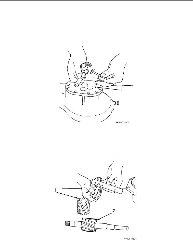
6. Use a hole gauge and a 0 to 1 in. micrometer to measure each bushing (Figure 16, Item 1) as indicated in step
5 for wear and out-of-roundness.
7. If replacement is necessary, water and oil pump housing bushings must be installed until they are flush to
0.015 in. (0.38 mm) below front surface of housing. Idler gear bushings must be installed in each end of gear
until they are approximately 0.125 in. (3.18 mm) below edge of gear.
Figure 16. Bushing Measurement.
0098
8. Use a micrometer to measure diameter of idler shaft (Figure 17, Item1) and drive shaft (Figure 17, Item 2).
Idler shaft diameter must be between 0.8635 to 0.8640 in. (21.993 to 21.946 mm). Drive shaft diameter must
be between 0.9875 to 0.9880 in. (25.083 to 25.095 mm). Replace any shaft not within specification.
Figure 17. Idler Shaft and Drive Shaft Measurement.
0098
0098-15

