
TM 5-3805-255-14
0104
DISASSEMBLY CONTINUED
Directional and Range Clutches
000104
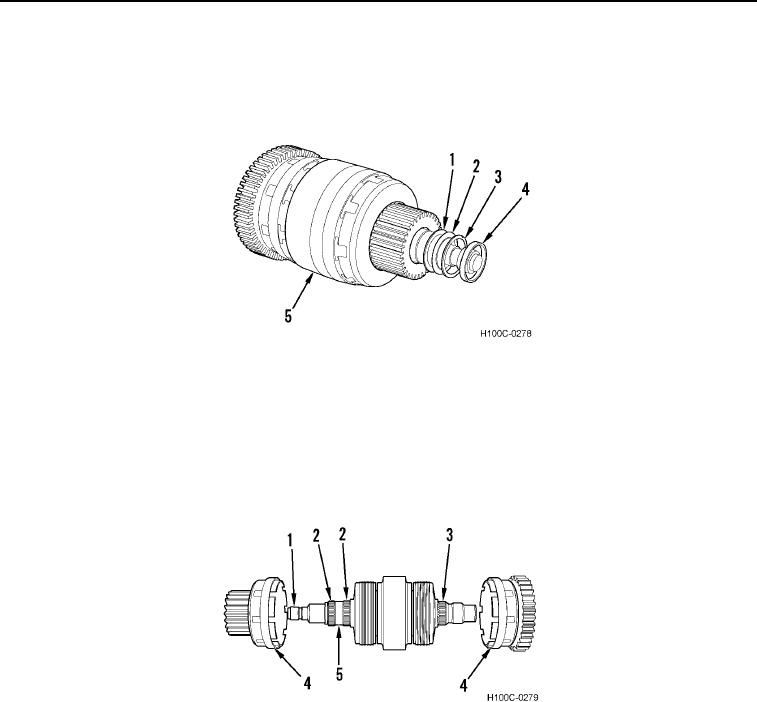
1. Remove spacer (Figure 3, Item 4), spacer (Figure 3, Item 3), thrust washer (Figure 3, Item 2), and spacer
(Figure 3, Item 1) from clutch shaft (Figure 3, Item 5).
Figure 3. Spacers and Thrust Washer Removal.
0104
CAUTION
Do not attempt to separate drive gear and cup. Failure to follow this caution may cause
damage to equipment.
2. Remove two gears (Figure 4, Item 4), bearings (Figure 4, Items 2 and 3) and spacers (Figure 4, Item 5) from
clutch shaft (Figure 4, Item 1).
Figure 4. Gear and Bearing Removal.
0104
0104-3