
TM 5-3805-255-14
0104
DISASSEMBLY
000104
Directional Clutches
000104
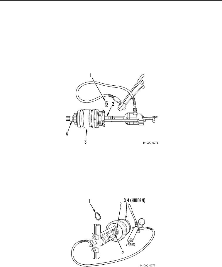
1. Remove snap ring (Figure 1, Item 1) and bearing inner race (Figure 1, Item 2) from clutch shaft (Figure 1,
Item 3). Discard snap ring.
CAUTION
Do not push directly on plug on end of shaft. Failure to follow this caution may cause
damage to equipment.
2. Remove bearing race (Figure 1, Item 4) from opposite clutch shaft (Figure 1, Item 3).
Figure 1. Directional Clutch Bearing Race Removal.
0104
Range Clutches
000104
1. Remove snap ring (Figure 2, Item 1) and bearing inner race (Figure 2, Item 2) from clutch shaft (Figure 2,
Item 5). Discard snap ring.
2. Remove snap ring (Figure 2, Item 3) and inner race (Figure 2, Item 4) from clutch shaft (Figure 2, Item 5).
Discard snap ring.
Figure 2. Range Clutch Bearing Race Removal.
0104
0104-2