
TM 5-3805-255-14
0104
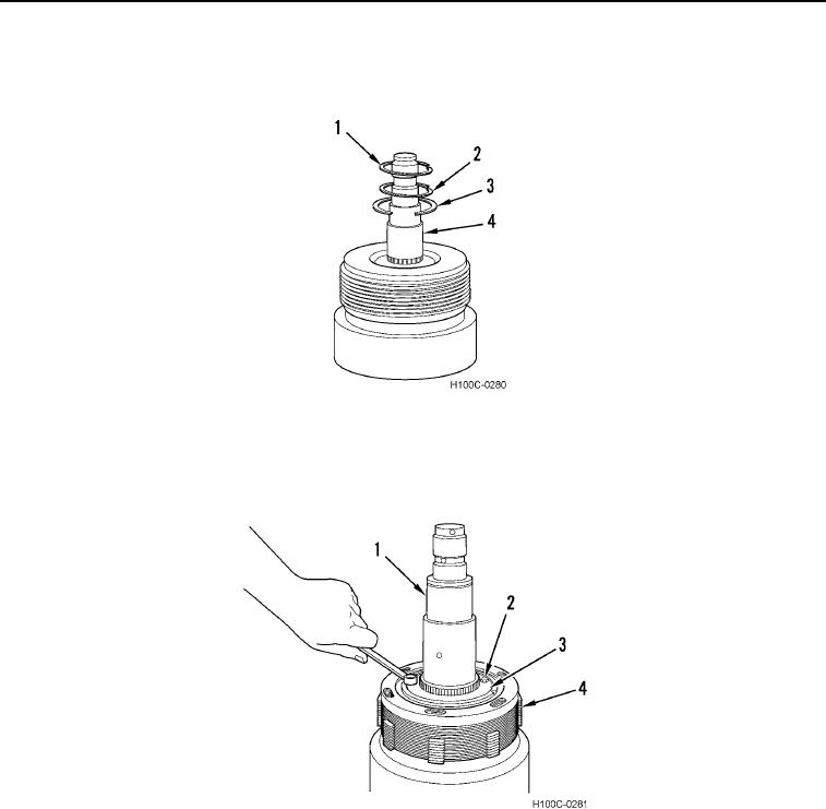
DISASSEMBLY CONTINUED
3. Remove spacer (Figure 5, Item 1), thrust washer (Figure 5, Item 2), and spacer (Figure 5, Item 3) from clutch
shaft (Figure 5, Item 4).
Figure 5. Spacers and Thrust Washer Removal.
0104
4. Remove two capscrews (Figure 6, Item 2), clutch hub retainers (Figure 6, Item 3), and hub and plate assembly
(Figure 6, Item 4) from clutch shaft (Figure 6, Item 1).
Figure 6. Clutch Hub and Plate Removal.
0104
0104-4