Engine Equipment
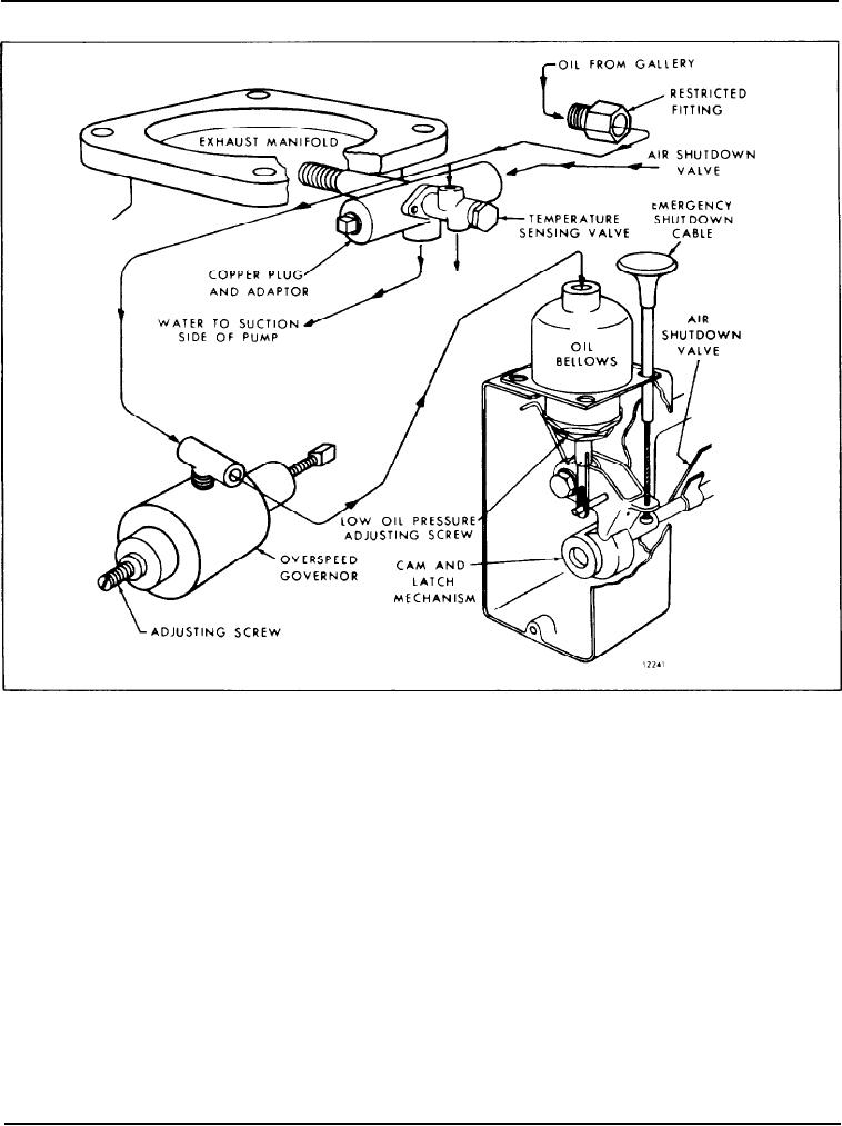
Fig. 4 - Schematic Drawing of Automatic Mechanical Shutdown System with Overspeed Governor
Check the operation of the engine coolant tempera-
attaching an air hose (40 psi or 276 kPa air supply) to
ture-sensing valve by placing a cover over the radiator
the oil inlet side and installing a tube from the outlet
while the engine is operating at part load and note the
side to a can of water. Then immerse the power
coolant outlet temperature at which the bellows
element of the valve in a container of water that is
disengages the air shutdown latch. The air shut-off
heated and agitated. Check the temperature of the
valve should close and stop the engine within a
water with a thermometer. Apply air to the valve. The
temperature range of 200-210 F (93-99 C). If the
valve should be open, as indicated by the flow of air.
engine is not shut down in this range, replace the
at a water temperature of 195-206 F (91-95 C).
temperature-sensing valve. If the engine is shut down
below 200 F (93 C), check the coolant flow through
To adjust the overspeed governor, start and run the
the plug and adaptor assembly and, if circulation is
engine until normal operating temperature is reached.
satisfactory, replace the temperature-sensing valve.
Then increase the engine speed to the desired
overspeed shutdown speed. At this speed, the bellows
NOTE: If a premature engine shutdown occurs,
should disengage the air shutdown latch and stop the
check the copper plug. A spring and plunger
engine. If necessary, adjust the overspeed governor
assembly are used with the current type plug to
setting by loosening the lock nut on the adjusting
provide an unobstructed flow of coolant over
the temperature-sensing valve element.
screw at the rear of the governor and turn the screw
clockwise to increase the shutdown speed or counter-
The temperature-sensing valve can be bench tested by
clockwise to decrease the shutdown speed. Then
Page 34

