Engine Tune-Up
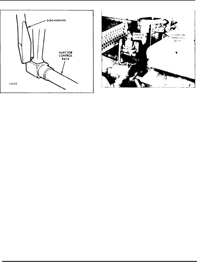
Fig. 6 - Governor Operating Lever in Position
Fig. 5 - Checking Injector Rack " Spring"
(SGX or PSG) will determine the proper position of
the lever (Fig. 6).
NOTE: Overtightening of the injector rack
control lever adjusting screws during installa-
15. Remove the gage.
tion or adjustment can result in damage to the
injector control tube. The recommended torque
16. Move the bell crank lever to the no-fuel position.
of the adjusting screws is 24-36 in-lbs (3-4
Nm).
17. Adjust the length of the vertical link so that the
bolt holes of the levers and the centers of the rod end
10. Recheck the No. 4R injector rack to be sure that it
bearings are lined up (Fig. 7).
has remained snug on the ball end of the injector rack
control lever. If the rack of No. 4R injector has
18. Replace the two bolts in the levers and tighten the
become loose, back off the inner adjusting screw
bolts.
slightly on the 3R injector rack control lever. Tighten
the outer adjusting screw. When the settings are
19. Remove the governor cover
correct, both injector racks must respond in the same
manner on the ball ends of their respective rack
20. With the load limit screw backed all the way out,
control levers as previously outlined in Step 7.
retain the governor operating lever in the full fuel
position. The governor terminal lever should touch the
11. Position the remaining injector rack control levers
boss on the governor housing. Adjust the vertical link
on the right front cylinder head as outlined in Step 9.
so that all of the injector racks are in the full fuel
When the settings are correct, all of the injector racks
position, then tighten the rod end lock nuts securely.
will be snug on the ball end of the control levers when
the injector control tube lever is held in the full-fue1
21. Use a new gasket and install the valve rocker cover
position.
on each cylinder head.
12. Adjust the remaining injector rack control levers
on the right rear, left front, and left rear cylinder
Adjust Load limit
heads in the same manner as outlined in Steps 9, 10
and 11.
The load limit is set at the factory and any further
adjustment should be unnecessary. However, if the
13. Remove the bolt from the recessed hole in the
governor has had major repairs, or the injector control
drive housing and install linkage gage J 21304.
rack levers have been re-positioned the load limit
screw should be re-adjusted.
14. Replace the governor operating lever on the
With the injector rack control levers properly adjusted,
serrated shaft so that the bolt hole is lined up within
set the load limit as follows:
the proper lines on the gage. The type of governor
Page 128

