Engine Tune-Up
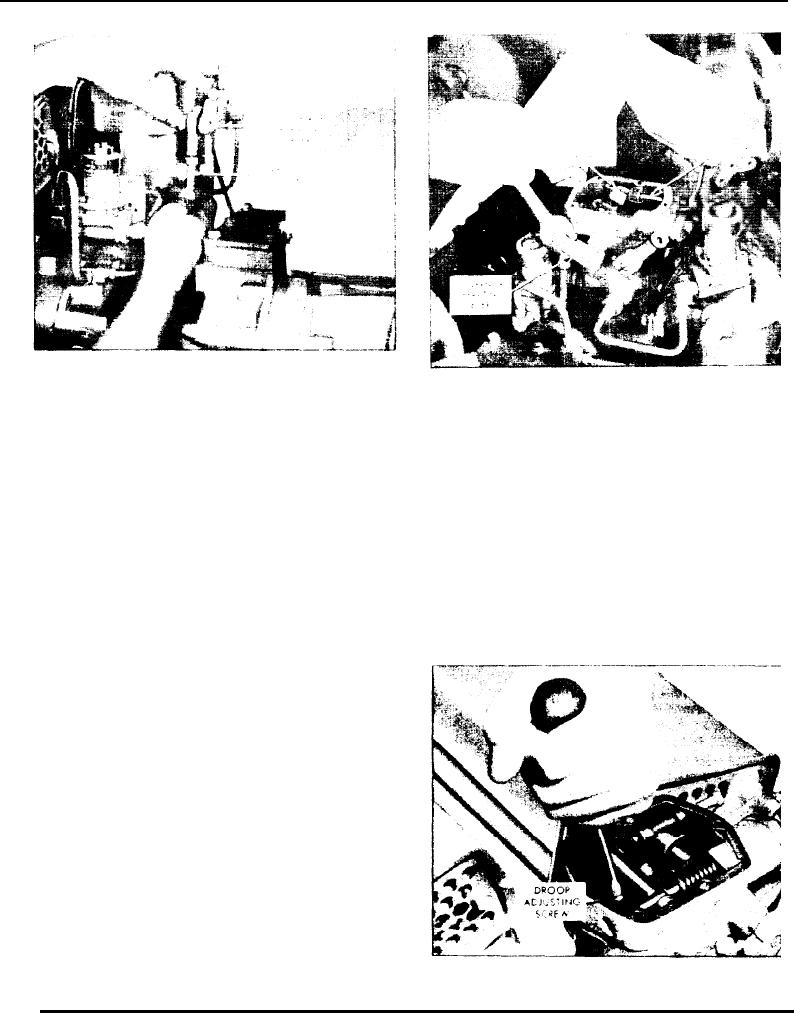
Fig. 8 - Adjusting Load Limit Screw
Fig. 7 - Adjusting Vertical Link
the valve completely and noting the number of turns
1. With the governor cover off and the load limit screw
lock nut loosened, place and retain the governor
required to close it. Open the valve to the previously
operating lever in the full-fuel position as shown in
determined position at which the "hunting" stopped.
Fig. 8.
Test the action of the governor by manually disturbing
the engine speed. The engine should return promptly
CAUTION: Do not overstress the linkage.
t o the original steady speed with only a small
overshoot. The correct valve setting will be between
2. Turn the load limit adjusting screw until a
1/8 and 1/2 turn open. Closing the valve farther than
.020" space exists between the fuel rod collar and the
terminal lever. If the adjustment cannot be made with
necessary will make the governor slow in returning the
a feeler gage, turn the load limit adjusting screw (with
engine to normal speed after a load change.
the lock nut tight enough to eliminate any slack in the
threads) in until the injector racks just loosen on the
ball end of the control levers.
3. Release the governor operating lever and hold the
adjusting screw while tightening the lock nut. Then
install the governor cover and tighten the screws.
Compensation Noodle Valve Adjustment (PSG
Govenor)
Start the engine and, after the engine reaches normal
operating temperature, adjust the governor compensa-
tion needle valve, without load on the engine, as
follows:
1. Open the valve (Fig. 10) two or three turns and
allow the engine to "hunt" or "surge" for about one-
half minute to bleed any air which may be trapped in
the governor oil passages.
Fig. 9 - Adjusting Speed Droop
2. Gradually close the valve until the "hunting" just
stops. Check the amount of valve opening by closing
Page 129

