Engine Tune-Up
move the slider all the way in toward the center of the
governor. Then tighten the knob.
6 . Loosen the lock nut on the maximum speed
adjusting screw and turn the screw out until 5/8" of
the threads are exposed.
7. With the engine operating at the recommended
full-load speed, apply the full rated load and recheck
the engine speed. If required, readjust the engine to
full-load speed.
8. Remove the load and note the engine speed. If the
zero droop setting is correct, the engine speed will
remain constant. If the engine speed is higher, loosen
the droop adjusting knob and set the slider to a
reduced droop position.
9 . When the desired minimum droop setting is
reached, loosen the lock nut and turn the minimum
droop setting screw in until it contacts the droop
linkage within the governor. This will be felt by a
step-up of resistance while turning the adjusting
screw. Lock the adjusting screw in this position.
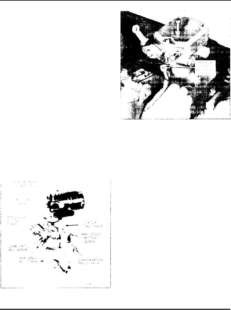
Fig. 11 - Adjusting Maximum No-Load Engine
Speed
10. Loosen the droop adjusting
knob and slide the
droop bracket in a direction to
increase the droop.
droop setting screw in until it contacts the droop slider
Perform Steps 7 and 8 to check
the droop until the
arm. Lock the adjusting screw in this position.
desired maximum speed droop is
attained.
1 2 . Recheck the minimum and maximum droop
11. When the desired maximum droop setting is
setting as outlined in Steps 7 and 8 and adjust the
reached. loosen the lock nut and turn the maximum
adjustment screws, if necessary, until the correct
settings are obtained.
Adjust Maximum No-load Speed
With the speed droop properly adjusted, set the
maximum no-load speed as follows:
1. With the engine operating at no-load, adjust the
speed until the engine is operating at approximately
8% higher than the rated full-load speed.
2. Turn the maximum speed adjusting screw (Fig. 11)
i n until the screw contacts the throttle linkage
internally, limiting the maximum speed of the engine
at 8% above the rated full-load speed.
3. Hold the screw and lighten the lock nut.
Adiust Low-Speed Stop Screw
The low-speed stop screw (Fig. 12) projects from the
top of the governor cover. This screw is used to
Fig. 10 - Typical Synchronizing Motor
establish an idle speed setting when the throttle is
Mounting
moved to the idle/neutral position on marine units,
Page 131

