An undercharged battery as evidenced by low
System output preferably should be checked at the
specific gravity readings and slow cranking.
"RATED VOLTAGE" given in the table.
An overcharged battery as evidenced by exces-
However, it IS permissible to check the output in
sive battery water usage.
amperes at any voltage within the "OPERATING
RANGE" listed in the table, since the current out-
These conditions can be caused by:
put will be quite close to the value that would be
o b t a i n e d a t " R A T E D VOLTAGE". The voltage
should never be allowed to rise above the "OPER-
I. A defective battery
ATING RANGE" for any length of time.
II. Poor circuit connections
III. A defective Integral Charging System
OPERATING
RATED
SYSTEM
I. BATTERY
RANGE
VOLTAGE
VOLTAGE
Since the battery may have an internal defect, it
26.0-30.0
28.0
24
must be checked to determine its condition. Ser-
vice Bulletin 7D-100E cover testing of batteries and
It should be noted that the voltage may be below
Energizers, respectively.
the "OPERATING RANGE" if the battery is in a
low state of charge. However, as the battery re-
II. CIRCUIT CONNECTIONS
ceives a charge, the voltage will rise to some value
within the "OPERATING RANGE."
Poor circuit connections in the 25 SI Integral
Charging System can cause an undercharged con-
dition only. Carefully Inspect all connections in-
c l u d i n g grounds between the Integral Charging
MAGNETIZING THE ROTOR
System and battery for cleanliness and tightness.
Insure that the battery cable clamps are clean and
The rotor normally retains magnetism to provide
tight, and that the battery IS dry and clean.
voltage build-up when the engine IS started. After
disassembly or servicing. however, it may be neces-
sary to re-establish the magnetism. To magnetize
III. INTEGRAL CHARGING SYSTEM
the rotor connect the Integral Charging System to
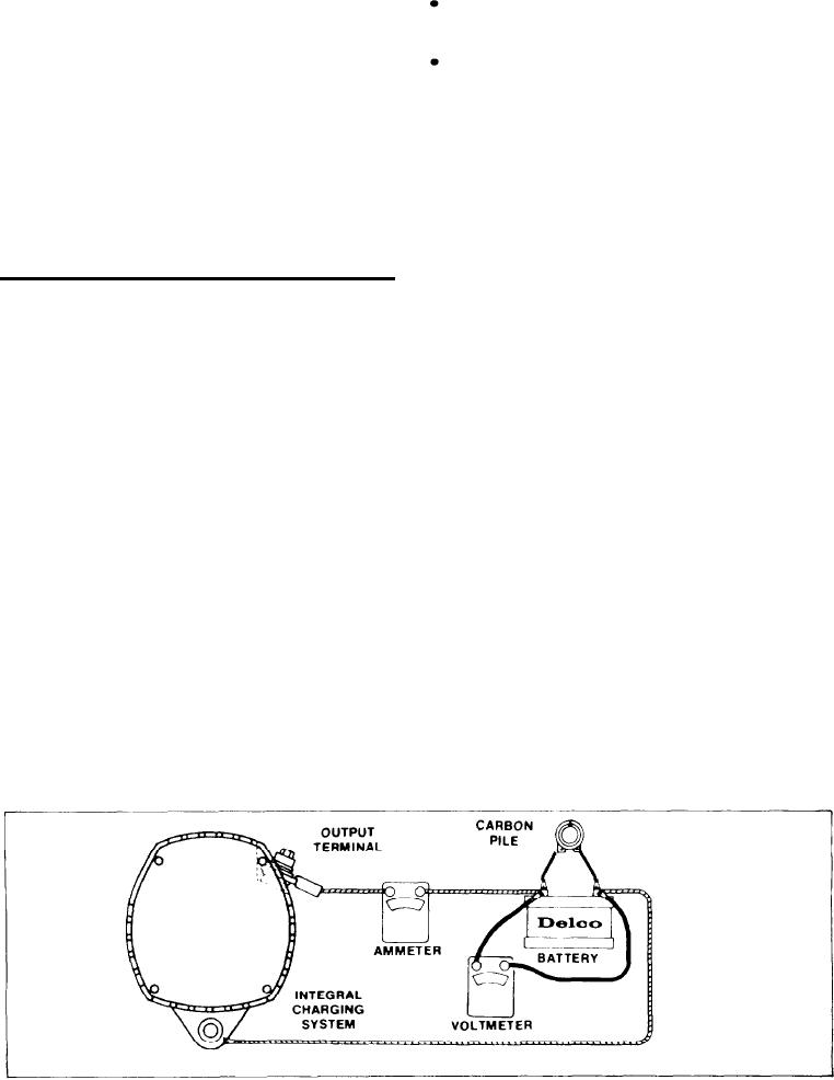
If the battery and circuit connection checks are
the battery in a normal manner, then momentarily
satisfactory, the Integral Charging System may be
connect a jumper lead from the battery positive
c h e c k e d either on or off the vehicle by making
post to the Integral Charging System relay terminal,
c o n n e c t i o n s as shown in Figure 4. Assemble a
identified in Figure 2. This procedure applies to
closed end terminal clip with 1/2 inch (12.7 mm)
b o t h negative and positive ground systems, and
hole to output terminal, then connect ammeter lead
will restore the normal residual magnetism in the
clip to this terminal clip.
rotor.
A
With the carbon pile turned off (open-
Trouble in the vehicle charging system will be
circuited), i n c r e a s e t h e I n t e g r a l C h a r g i n g
indicated by one of two conditions:
Figure 4--Output check (Remember-the hex bolt on the output terminal is electrically insulated)
[60]

