Motor: If the battery, wiring and switches are in
OPERATION
satisfactory condition. and the engine is known to
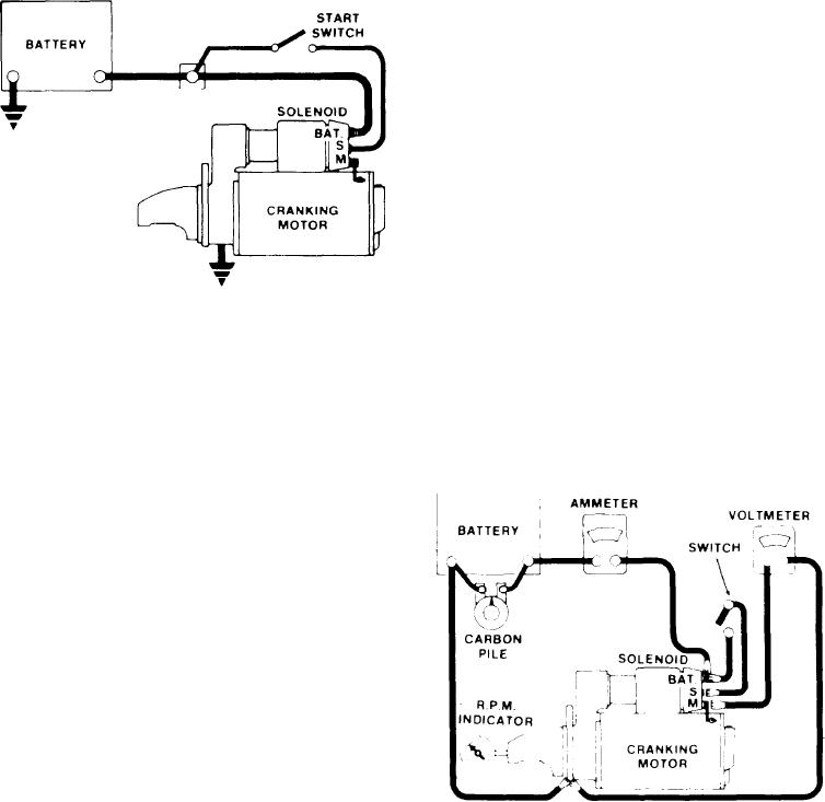
In the basic circuit shown in Figure 3. the sole-
be functioning properly, remove the motor and fol-
n o i d windings are energized when the swith is
low the test procedures outlined below.
closed The resulting plunger and shift lever move-
ment causes the pinion to engage the engine fly-
wheel ring gear and the solenoid main contacts to
CRANKING MOTOR TESTS
close, pinion overrun protects the armature from
excessive speed until the switch is opened. at which
R e g a r d l e s s of the construction. never operate
time the return spring causes the pinion to disen-
the cranking motor more than 30 seconds at a time
gage To prevent excessive overrun and damage to
without pausing to allow it to cool at least two min-
the drive and armature windings. the switch must
u t e s . On some appications. 30 seconds may be
be opened immediately when the engine starts.
excessive. Overheating. caused by excessive crank-
ing will seriously damage the cranking motor.
With the cranking motor removed from the en-
gine. the armature should be checked for freedom
of rotation by prying the pinion with a screwdriver
Tight bearings. a bent armature shaft. or a loose
pole shoe screw will cause the armature to not turn
freely. If the armature does not turn freely the mo-
tor should be disassembled immediately. However.
if the armature does rotate freely. the motor should
be given a no-load test before disassembly
No-Load Test (Fig. 4)
Connect a voltmeter from the motor terminal to
the motor frame. and use an r.p.m. indicator to mea-
s u r e armature speed. Connect the motor and an
ammeter in series with a fully charged battery of
Figure 3-Basic wiring circuit.
the specified voltage. and a switch in the open po-
sition from the solenoide battery terminal to the
s o l e n o i d e switch terminal Close the switch and
TROUBLESHOOTING THE
compare the r p m c u r r e n t and voltage reading
CRANKING CIRCUIT
with the specifications in Service Bulletins 1M-86
or 1M-187. It IS not necessary to obtain the exact
voltage specified in these bulletins. as an accurate
Before removing any unit in a cranking circuit
interpretation can be made by recognizing that if
for repair. the following checks should be made:
Battery: To determine the condition of the bat-
tery. follow the testing procedure outlined in Ser-
vice Bulletin 7D-100E Insure that the battery IS
fully charged
Wiring: Inspect the wiring for damage. Inspect
all connections to the cranking motor. solenoide.
magnetic switch. ignition switch or any other con-
trol switch and battery). Including all ground con-
nections Clean and tighten all connections as
required
Magnetic Switch, Solenoide and Control Switches:
Inspect all switches to determine their condition
Connect a jumper lead around any switch suspected
of being defective If the system functions properly
using this method. repair or replace the bypassed
Figure 4-No-load test circuit
switch.
[68]

