
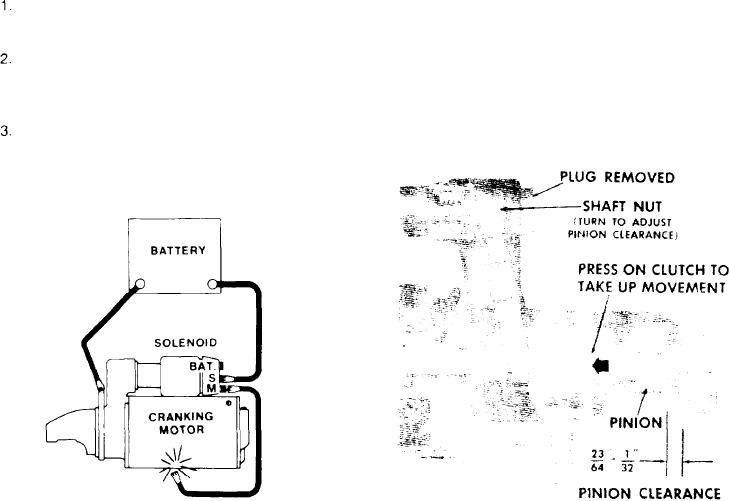
cranking position and remain so until the battery
PINION CLEARANCE
is disconnected.
To check pinion drive clearance follow the steps
4. Push the pinion or drive back towards the com-
listed below.
mutator end to eliminate slack movement.
Disconnect the motor field coil connector from
5. Measure the distance between drive and drive
the solenoid motor terminal.
stop (Figs. 9, and 22).
Connect a battery. of the same voltage as the
6. Adjust clearance by removing plug and turning
solenoid. from the solenoid switch terminal to the
shaft nut (Figs. 9). The clearance for the Position
solenoid frame or ground terminal (Fig. 8).
d r i v e (Fig. 2) IS the same as that shown in
Figure 9.
MOMENTARILY flash a jumper lead from the
solenoid motor terminal to the solenoid frame or
ground terminal. The drive will now shift into
Figure 9.
Figure 8-Circuit for checking pinion clearance.
[72]