TM 5-3805-258-10
WARNING
Point quick disconnect fittings away from your-
self, other personnel, and any part of the machine
which might become damaged from the spraying
hydraulic fluid when pressure is relieved.
13. Reconnect all hydraulic and air hoses with quick
disconnects and all electrical connectors. Use tags for
easy identification. Store plug for air line in the
bracket just beneath where the lines are connected.
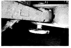
10. To install the lower pin spacer, use a flashlight while
observing alignment of bores from under the machine,
adjust the jacks as necessary, and use the 3-1/2 and
2-3/4 in. bolts to push the lower pin spacer in place.
Reinstall shims and lower retainer plate and tighten
all pin retaining bolts.
14. Using the 2-1/2 in. open end striking wrench and a
hammer, disconnect the two large main hydraulic
hoses from one another, and reconnect them to the
front frame connectors. Use a small hammer on the
wrench to tighten the connections.
11.
12,
CAUTION
Never start the engine with the large hoses discon-
nected.
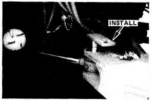
Remove the articulation cylinder pins and start the
engine. While another person slowly turns the steering
wheel, align the pin bores and tap the pins in place.
Be careful not to damage the rod end bushings. Stop
the engine. Install bolts and washers.
Loosen the hydraulic tank filler cap to relieve any air
pressure in the tank.
NOTE
If pressure at the quick disconnect fittings pre-
vents easv coupling of the lines, push a smooth,
clean, rounded-end rod into each coupling to
relieve the pressure, being careful not to damage
the connector seals.
15.
16.
17.
18.
19.
20.
21.
Reinstall the steering neutralizer valve stops.
Reinstall bracket for two air hoses that cross over
upper hitch pin and reinstall cockpit floor plate.
Remove the skid support braces and turn the skid
support jack screws in to relieve any load. Remove
the skid supports and reinstall the tie-down eyes.
Turn the skid support jack screws all the way in and
tighten the set screws and jam nuts. Using two persons,
raise the skid supports and secure them to the hood.
Unbolt the rear anti-tip skids and reattach them in
their upright stowed position.
Remove chain securing the bucket lifting arm linkage,
and remove and store the jacks.
Start the engine and move the bucket down to raise
the front wheels off the ground. Stop the engine.
Rotate the front wheels by hand to align the drive
shaft with the mating flange on the front frame. Start
the four bolts through the U-joint bearing caps and
into the mating flange. Use a 3/8 in. 12-point socket
with a 3/8 in. universal and 3/8 in. drive with a 5 in.
long extension to tighten the four bolts.
94