TM 5-3805-258-24-2
DISASSEMBLY AND ASSEMBLY
ENGINE
ENGINE
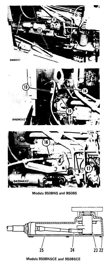
10. Connect fuel lines (11) to the fuel injection
pump housing and at the rear of the engine.
11. Connect fuel line clips (12) to the oil pan.
12. Connect wire harnesses (13), (14) and (15)
at the rear of the engine.
13. For Models 950BNS and 950BS:
a) Connect bracket (17) to governor.
b) Connect cable assembly (16) to governor
control lever.
14. For Models 950BNSCE and 950BSCE:
a)
b)
c)
d)
Install housing (22) and two screws.
Turn governor shaft clockwise to off
position. Install lever (23) and bushings
with lever approximately 35° forward
of vertical.
Connect cable assembly (24) using washer
and screw.
Install gasket, cover (25) and six screws.
5-154

