TM 5-3805-258-24-2
ENGINE
DISASSEMBLY AND ASSEMBLY
ALTERNATOR
ASSEMBLE ALTERNATOR
3T1888 (Delco-Remy)
1.
2.
3.
4.
5.
6.
7.
8.
9.
10.
11.
12.
13.
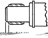
If removed, install hinge bushing (5O).
If removed, install bearing race (49)
dimension shown on the right.
to the
INNER RACE LOCATION
If removed, install bearing (48) into housing
(44) until bearing is flush with the inside of
the housing.
Install cap (47).
Apply a light coating of silicone grease to
grommet (52) and pull stator wiring into
housing (44).
Attach field coil (46) and stator (45) to
housing (44) with three screws (43).
Position wiring grommet (42) in stator
housing.
Secure rectifier bridge (26) with insulator
(41), washers (40 and 39), and screw (38).
Secure lead assembly (37) with screw (36).
Install alternator output terminal (35).
Secure regulator (34) with mounting screw
(33).
Secure field coil leads with lockwashers (32),
washers (31), screws (30), lockwasher (29),
and nut (28).
Position the wiring on the rectifier bridge in
this order:
(1) On each of the three rectifier studs,
position two diode leads.
(2) Next, place a stator lead on each stud.
(3) Position the “R” terminal (37A) lead
over one of the studs.
14.
15.
16.
17.
18.
19.
20.
21.
22.
23.
24.
25.
(4) Secure wiring with three nuts (27).
Position gasket (25) and cover (24) on stator
housing.
Install five lockwashers (23) and screws (22),
Install two lockwashers (21) and screws (20).
Secure regulator cover (19) with lockwashers
(18) and four screws (17).
Press bearing (16) into end frame (6) until
bearing is flush with the inside surface of the
end frame (6).
Install seal (15) and collar (14).
Install seal (13), collar (12).
Secure retainer (10) and gasket (11) with
four screws (9).
Install shield (8).
Press rotor (7) into end frame (6).
Attach the end frame/rotor assembly to the
stator housing with lockwashers (5) and
bolts (4).
Install fan (3).
Position alternator in a vise or similar clamp-
ing device.
CAUTION
Be careful not to overtighten alternator in vise.
Damage to the alternator is possible if the vise is
overtightened.
26.
27.
Place alternator pulley on alternator and
secure with washer (2) and locknut (1).
The alternator rotor usually retains mag-
netism to provide voltage buildup when the
engine is started. However, after disassembly
or servicing it may be necessary to reestablish
the magnetism. Perform the following pro-
cedures to demagnetize the rotor.
(1) Install the alternator.
(2) Momentarily connect a jumper lead
from the battery positive post to the
“R” terminal (37A).
5-12m


