TM 5-3805-258-24-2
ENGINE
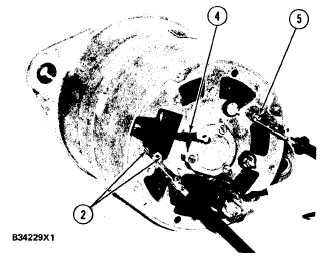
Winding To Frame Test
Connect ohmmeter between the (B–) terminal and
each of the two field coil winding leads (2). Each of
the two readings should be high (indicating no shorts
to frame).
POLE BODY WINDING TO FRAME TEST
2. Field winding leads. 4. Rectifier bridge lead. 5. Terminal
( B - ) .
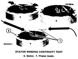
Stator Test
Stator Winding Continuity Test
TESTING
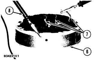
Stator Winding to Frame Test
Connect the ohmmeter between each of the three
stator windings and the frame (three readings). Re-
sistance values should be very high (an indication of
no shorts to frame).
STATOR WINDING TO FRAME TEST
(Test Other Two Leads As Shown)
6. Stator. 7. Phase leads. 8. Test lead to frame.
Rectifier Test
Unsolder stator winding leads (7) from rectifier and
remove stator (6). Disconnect capacitor lead from
(D+) terminal. On the ohmmeter checks that fol-
low, make one check then reverse the ohmmeter
leads. One reading should be high and one low. If not,
the rectifier has a defect and should be replaced.
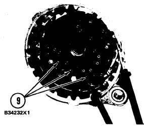
Minus Diode Check
Connect ohmmeter between each rectifier solder
phase terminal (9) and the frame (ground).
Remove stator (6) from frame assembly. Connect
ohmmeter between pairs of the three stator winding
leads (7) (three readings). Resistance should be .15
to .25 ohms.
If the resistance test values are not correct, then the
stator (6) has a defect.
MINUS DIODE CHECK
9. Bridge rectifier terminals.
5-12h