OPERATOR’S STATION
ADJUSTABLE STEERING
3.
4.
5.
6.
7.
8.
9.
10.
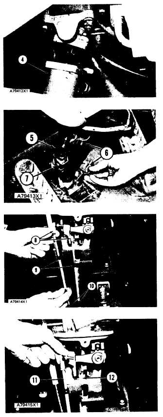
Install hand metering pump (4) on the steering
column assembly.
Put transmission cables (5) and parking brake
cable in position in the steering column support.
Put bracket assembly (7) in position on the steer-
ing column. Install clamps (6) on the bracket
assembly.
Install the nuts that hold the transmission cable
assemblies in position on the steering column
support.
Install seals (9) and (10) on the cable assemblies.
Install ballpoints (8) on the cable assemblies.
Turn the handle on the transmission control lever
to the “FIRST” speed.
Connect speed control cable assembly (12) to the
rack on the transmission control.
NOTE: On models 950BNSCE and 950BSCE,
put washer on threaded stud of control cable
assembly (11) ball joint.
Put the transmission control lever in the “NEU-
TRAL” position. Connect direction control ca-
ble assembly (11) to the bellcrank on the trans-
mission control.
NOTE: Make an adjustment to the transmission con-
trol linkage.
See TRANSMISSION CONTROL
LINKAGE ADJUSTMENTS in POWER SHIFT
TRANSMISSION TESTING AND ADJUSTING.
TM 5-3805-258-24-2
DISASSEMBLY AND ASSEMBLY
COLUMN
5-509


