TM 5-3805-262-20
INSTALLATION (SHEET 2 OF 2)
(7) If necessary, adjust positioning of hose (21) on manifold (18) and con-
nector (22), Position clamps (20) on ends of hose (21) and tighten
clamps.
(8) Install U-bolt (17) on manifold (18); secure to bracket (26) using two
washers (16), lock washers (15), and capscrews (14).
(9) Route hose (9) between hydraulic reservoir and hydraulic pump.
(10) Place new 0-ring (10) in hose (9) fitting.
(11) Connect hose (9) to manifold (18).
(12) Position two tube flanges (8) and install and tighten four lock washers
(7) and capscrews (6).
(13) Install clamp (5) on end of hose (9).
(14) Connect hose (9) to hydraulic reservoir by firmly pushing hose onto hy-
d r a u l i c r e s e r v o i r p o r t ; t i g h t e n c l a m p ( 5 ).
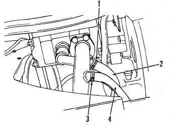
(15) Install clamps (1 and 3) on end
of hoses (2 and 4).
(16) Connect hoses (2 and 4) toman-
(17)
(18)
(19)
ifold ports by firmly pushing
hoses onto ports.
Position clamps (1 and 3) on
end of hoses (2 and 4) and
t i g h t e n s e c u r e l y .
F i l l h y d r a u l i c r e s e r v o i r w i th
oil (page 11-79).
Start engine and operate at
idle speed. With engine opera-
t i n g a t i d l e s p e e d , t u r n s t e e r-
ing wheel to right and then to
left several times to remove
any air from steering system.
(20) Move hydraulic control levers in both directions several times to remove
any air from hydraulic system.
(21) Lower bucket to floor and turn off engine. Check for oil leakage at all
connections. Tighten connections as necessary.
(22) Check hydraulic reservoir oil level; add oil as necessary (page 11-78).
( 2 3 ) I n s t a l l e n g i n e r i g h t s i d e p a n e l s ( p a g e 9 - 1 7 ) .
11-31