TM 5-3805-262-20
3-12. SENDING UNITS TROUBLESHOOTING (CONT)
MALFUNCTION
TEST OR INSPECTION
CORRECTIVE ACTION
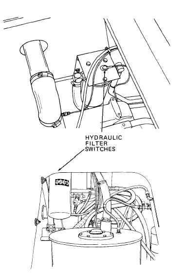
9. HYDRAULIC FILTER SWITCH DOES NOT OPERATE.
Step 1.
Remove engine left side
panels (page 9-14) and
open front access door.
Disconnect gray-white
wires from terminals of
b o t h h y d r a u l i c f i l t e r
switches (pages 8-43 and
11-82).
Connect multimeter be-
tween terminal of each
h y d r a u l i c f i l t e r s w i t c h
and ground.
Multimeter should indi-
cate continuity for each
switch.
a . I f m u l t i m e t e r i n d i -
cates continuity, go
to step 2 below.
b. If multimeter does
n o t i n d i c a t e c o n t i-
n u i t y , r e p l a c e h y -
d r a u l i c f i l t e r
switch (page 8-43 or
11-84).
Step 2.
Start engine and connect
multimeter between ter-
minal of each hydraulic
f i l t e r s w i t c h a nd
ground.
Multimeter should indi-
cate no continuity (open
c i r c u i t ) f o r e a c h
switch.
a . I f m u l t i m e t e r i n d i c a t e s c o n t i n u i t y , r e p l a c e h y d r a u l i c f i l t er
element (page 8-40 or 11-82) and repeat step 2. If multimeter
i n d i c a t e s c o n t i n u i t y a f t e r f i l t e r c h a n g e , r e p l a c e h y d r a u l ic
filter switch (page 8-43 or 11-84) .
b. If multimeter does not indicate continuity, refer to page 3-75,
MALFUNCTION 5.
3-98


