TM 5-3805-262-20
1-18. FUEL SYSTEM (CONT)
3. AIR PRECLEANED AND CLEANER.
Two stage filter containing a primary filter and a
s e c o n d a r y f i l t e r . A i r r o u t e d t o c y l i n d e r s i s f i l t e r e d t h r o u g h b o t h t h e s e f i l t e r s.
Thus, dust and dirt reaching engine is held to a minimum. Air compressor receives
its input air via air cleaner by a fitting connected to air cleaner adapter mounted
on intake manifold.
4. FUEL TANK AND LINES AND FITTINGS.
Fuel tank holds approximately 58 gallons of
D i e s e l f u e l ;
located at rear of loader. Fuel filler neck and removable cap located
at right rear of loader and is accessible by removing right rear side panel. Drain
plug located at bottom of fuel tank . Fuel lines and fittings connect fuel tank to
electric fuel pump, first and second stage fuel filters, and to fuel injection pump .
5. ELECTRIC FUEL PUMP.
Pumps Diesel fuel from fuel tank to fuel filters then to
fuel injection pump. Mounted on front center of fuel tank. With ignition key switch
in on position, fuel pump will emit a slight buzz indicating proper operation. Pump
consists of coil, plunger, and breaker points. With coil energized, plunger moves in
plunger bore which opens and closes breaker points. With plunger at top of plunger
tube, breaker points are closed. Coil is then energized, and plunger is pulled to
bottom of plunger tube compressing plunger spring. Check valve in plunger opens and
fuel flows through plunger. With plunger at bottom of plunger tube, breaker points
are opened and coil is deenergized. Plunger spring returns plunger to top of plunger
tube. During up stroke of plunger, check valve is closed and fuel is pushed into
fuel line. Valve at bottom of plunger tube opens and fuel flows into bottom of
plunger tube for next cycle.
6. COLD START KIT.
Consists of push type switch mounted on right instrument panel,
solenoid mounted on cold start cylinder, and atomizer installed in engine intake
manifold. Cold start cylinder mounted in engine compartment, on left post near en-
gine. COLD START switch operates only when ignition key switch is in Start position.
Depressing COLD START switch energizes solenoid,
spraying ether into engine intake
manifold only when engine cranked.
7. ACCELERATOR.
Consists of accelerator pedal connected by cable to fuel injection
pump and fuel shutoff control connected to fuel injection pump fuel shutoff lever .
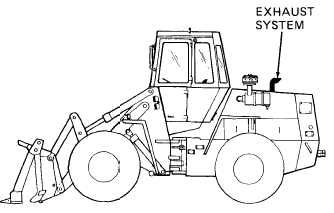
1-19. EXHAUST SYSTEM
Consists of muffler and tail pipe. Muffler quiets noise
from engine operation. Connected to exhaust manifold and
m o u n t e d a b o v e e n g i n e . T a i l p i p e c h a n n e l s e n g i n e
combustion byproducts from muffler to rear of loader.
1-20. COOLING SYSTEM
1. RADIATOR.
Engine coolant circulated
through radiator giving up its heat to air
stream developed by belt driven fan. Cooled
coolant drawn from bottom of radiator by
water pump and discharged into lower part
of cylinder block. Radiator also has cooler
built into its bottom for cooling transmission hydraulic oil. Radiator located at
r e a r o f l o a d e r.
1-16