TM 5-3805-262-20
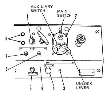
1-23. RIGHT INSTRUMENT PANEL Also see FO-3
I n c l u d e s a l l s w i t c h e s a n d i n d i c a t o r s f o r o p e r a t i n g l i g h t s , p a r k i n g b r a k e , s t a r t i ng
and stopping engine, dimmer control, and a HYDRAULIC FILTER warning indicator.
1. IGNITION KEY SWITCH,
Four position key switch.
Accessory Position (Maintained). Extreme left position. Applies power to Vehicle
Lights switch and instrument panel cluster.
Off Position (Maintained). Center position. Electrical system off.
Run Position (Maintained). First right position. Normal operating position after
engine started. Applies power to Vehicle Lights switch, instrument panel cluster,
a n d r e t u r n - t o - d i g a n d h e i g h t c o n t r o l c i r c u i t s.
Start Position (Spring Return to Run Position).
Applies power to COLD START switch,
s t a r t e r r e l a y v i a n e u t r a l s t a r t s w i t c h i n s t a l l e d i n t r a n s m i s s i o n c o n t r o l v a l v e , a nd
return-to-dig and height control circuits. With power applied to starter relay,
starter solenoid will energize, kicking in starter to turn engine flywheel and start
engine. When released, Ignition Key switch will return to Run position.
2. VEHICLE LIGHTS SWITCH.
C o n t r o l s a l l v e h i c l e l i g h t s , i n c l u d i n g s t o p l i g h t a t r e ar
of vehicle. Main switch has five positions and auxiliary switch has four positions.
UNLOCK lever must be in UNLOCK to move Main switch in B.O. DRIVE, STOP LIGHT, and
SER. DRIVE positions.
Main Switch B.O. DRIVE.
Power from pin F routed out pins A, D, and E to enable stop
light switch (pin A), turn on front black out driving light (pin D), and turn on
black-out tail light (pin E). When brake treadle is pressed, black-out stop light
will turn on (pin N). Auxiliary switch can
Main Switch B.O. MARKER.
Power from pin F
light switch (pin A) and turn on black out
pressed, black-out stop light will turn on
p o s i t i o n.
be in any position.
routed out pins A and E to enable stop
t a i l l i g h t ( p i n E ) . When brake treadle is
(pin N). Auxiliary switch can be in any
1-21


