TM 5-3805-262-20
3-32. CHARGING SYSTEM TROUBLESHOOTING (CONT)
MALFUNCTION
TEST OR INSPECTION
CORRECTIVE ACTION
1. ALTERNATOR NOT CHARGING BATTERIES (Cont).
S t e p 1 . ( C o n t ).
a. If VTM
panels
displays 26.5 to 31 volts, go to page 3-77, instrument
troubleshooting, MALFUNCTION 6.
b. If voltage is less than 26.5 volts, go to
c. If voltage is more than 31 volts, replace
5-10).
step 2 below.
a l t e r n a t o r ( p a ge
Step 2.
Connect test probe cable W2 connector P1 to VTM J4.
Dial 01 into VTM TEST SELECT and press and release TEST.
When PASS appears on VTM display, dial 89 into TEST SELECT.
Connect test probe cable W2 red test clip to black test clip.
Press and hold TEST until CAL appears on display then release TEST.
Wait for offset value to appear on display. Offset value should be
between -6.8 to +6.8. If it is not, STE/ICE is defective (refer to
TM 9-4910-571-12&P).
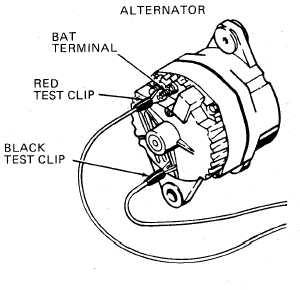
Alternator BAT terminal is connected to battery positive post. Be care-
ful when connecting test clip to alternator BAT terminal. If you acci-
d e n t l y s h o r t B A T t e r m i n a l t o m e t a l p a r t o f a l t e r n a t o r , b a t t e r i e s c o u ld
e x p l o d e c a u s i n g d e a t h o r s e r i o us
i n j u r y t o p e r s o n n e l s t a n d i n g n e a r
b a t t e r i e s .
Connect test probe cable W2 red
test clip to alternator BAT
terminal and black test clip to
loader or alternator frame.
Start engine and depress accel-
erator to obtain 1700 to 1900
rpm. VTM will alternately dis-
play engine rpm and battery
v o l t a g e.
Turn all loader driving lamps,
flood lights, and accessories
on to load charging system.
VTM display should indicate
26 . 5 to 31 volts.
3-257