TM 5-3805-262-20
3-32. CHARGING SYSTEM TROUBLESHOOTING (CONT)
MALFUNCTION
TEST OR INSPECTION
CORRECTIVE ACTION
1. ALTERNATOR NOT CHARGING BATTERIES (Cont).
S t e p 6 . ( C o n t ).
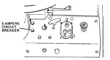
b. If VTM displays over (TBD) amperes, a short circuit exists. If 5
a m p e r e c i r c u i t b r e a k e r b l o w s , s h o r t c i r c u i t i s i n e i t h e r e l e c-
tric fuel pump, cab relay solenoid, left instrument panel clus-
ter, voltmeter, or orange-black wire connected between 5 ampere
circuit breaker’ and relay socket assembly. If 5 ampere circuit
breaker does not blow, check wiring between ignition key switch
ACC terminal and vehicle lights switch connector for short
circuit. Refer to wiring diagram, pages FO-7 and FO-9.
Step 7.
Dial 90 into VTM TEST SELECT.
Press and hold TEST button until CAL appears on VTM display then re-
lease TEST button.
Wait for offset value to appear on display. Offset value should be
between -225 to +225. If it is not, STE/ICE is defective (refer to
TM 9-4910-571-12&P).
Press and release TEST button.
Put vehicle lights switch auxiliary switch in PANEL BRT. position.
Turn DIMMER COMPT LIGHTS CONTROL on right instrument panel fully
counterclockwise.
Turn ignition key switch to accessory position (first counterclock -
w i s e p o s i t i o n ).
VTM display should indicate (TBD) amperes.
Turn ignition key switch to off position.
a. If VTM displays (TBD) amperes, go to step 8 below.
b. If VTM displays over (TBD) amperes, a short circuit exists.
Short circuit is in cab dome light or vehicle lights switch.
Refer to wiring diagram, pages FO-7 and FO-9.
3-261


