TM 5-3805-262-20
3-31. FUEL SYSTEM TROUBLESHOOTING (CONT)
MALFUNCTION
TEST OR INSPECTION
CORRECTIVE ACTION
1. LOW PURL PRESSURE (Cont).
S t e p 8 . ( C o n t ).
a .
b .
If VTM display indicates 3.2 to 9 psi, use compressed air to
clear blockage from fuel supply hose. Disconnect transducer
cable W4 from pressure transducer. Remove pressure transducer,
adapter, and street elbow from electric fuel pump port.
Reinstall elbow and fuel supply hose between elbow and fuel
injection pump feed pump.
If VTM display does not indicate 3.2 to 9 psi, go to step 9
below.
Step 9.
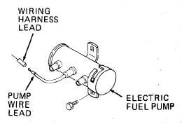
Disconnect electric fuel pump
terminal from wiring harness
terminal. Do this by grasping
terminals with your fingers and
f i r m l y p u l l i n g a p a r t.
Connect test probe cable W2 connec-
tor P1 to VTM J4.
Connect test probe cable W2 red test
c l i p t o b l a c k t e s t c l i p .
Dial 89 into TEST SELECT.
Press and hold TEST until CAL ap-
pears on display then release TEST.
Wait for offset value to appear on display. Offset value should be
between -6.8 to +6.8. If it is not, STE/ICE is defective (refer to
TM 9-4910-571-12&P).
C o n n e c t t e s t p r o b e c a b l e W 2 r e d t e s t c l i p t o w i r i n g h a r n e s s t e r m i n a l
and black test clip to loader frame.
Tell assistant to turn ignition key switch to on position.
Press and release TEST button.
VTM display should indicate 24 volts.
Tell assistant to turn ignition key switch to off position.
Disconnect test probe cable W2 test clips.
a . I f V T M d i s p l a y i n d i c a t e s 2 4 v o l t s , r e c o n n e c t e l e c t r i c f u e l p u mp
terminal and wiring harness terminal. Do this by grasping termi-
nals with fingers, alining, and firmly pushing together. Go to
step 10 below.
b. If VTM display does not indicate 24 volts, check for open cir-
cuit between wiring harness terminal and ignition key switch.
Repair or replace wire as necessary (page 5-168 or 5-174).
3-253