TM 5-3805-262-20
INSTALLATION (SHEET
(7)
( 8 )
( 9 )
(10)
(11)
(12)
(13)
(14)
(15)
P o s i t i on
2 OF 2)
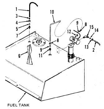
two compression nuts
(8) and compression sleeves (9)
on fuel suction tube (10) .
I n s t a l l f u e l s u c t i o n t u b e ( 1 0 ),
with compression sleeves (9)
and compression nuts (8) in-
s t a l l e d , t h r o u g h f i t t i n g ( 1 1 )
until tube (10) touches bottom
of fuel tank. Position compres -
s i o n s l e e v e ( 9 ) i n f i t t i ng
(11), then tighten compression
nut (8) securely using open end
wrench.
Connect opposite end of fuel
suction tube (10) to elbow
(12). Position compression
sleeve (9) in elbow (12) then
tighten compression nut (8)
securely using open end wrench.
I n s t a l l f i t t i n g ( 7 ) i n f u e l
tank and tighten securely using
open end wrench.
Position compression sleeve (5) and compression nut (4) on tube (6);
install tube (6) through fitting (7) until tube touches bottom of fuel
tank. Position compression sleeve (5) in fitting (7) and tighten
compression nut (4) securely using open end wrench.
Place clamp (3) on tube (6).
Connect fuel return hose (1) to
t u b e ( 6 ) .
Using pliers, expand clamp (3)
and position clamp over fuel
return hose (1) to secure it to
tube (6). Release clamp (3).
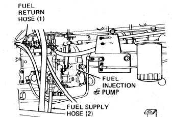
Reconnect fuel supply hose (2)
and fuel return hose (1) to
fuel injection pump. Tighten
fittings securely using open
end wrench.
Bleed air from fuel system (page 4-40).
Start engine and run at idle speed. Check hoses, lines, and fittings
installed above for fuel leakage. Tighten fittings if necessary. Shut
engine off.
Reinstall engine side panels (page 9-17).
4-13