TM 5-3805-262-20
4-2. FUEL SYSTEM MAINTENANCE (CONT)
d. A i r C l e a n e r ( c o n t ) .
(2) Replacement (cont).
INSTALLATION (SHEET 1 OF 2)
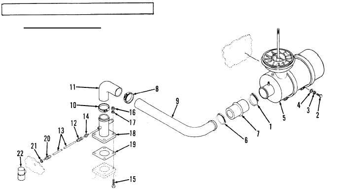
( a ) P o s i t i o n r e s t r i c t i o n i n d i c a t o r ( 2 2 ) o n h o o d s u p p o r t . P o s i t i o n l o ck
w a s h e r ( 2 1 ) o n f i t t i n g ( 2 0 ) t h e n i n s t a l l f i t t i n g t o s e c u r e r e s t r i c t i on
indicator.
(b) Position gasket (19) and adapter (18) on intake manifold; secure using
four capscrews (15), lock washers (17), and nuts (16).
( c ) I n s t a l l a d a p t e r ( 1 4 ) i n a d a p t e r ( 1 8 ) ; t i g h t e n s e c u r e l y .
( d ) I n s t a l l c o n n e c t o r ( 1 2 ) i n a d a p t e r ( 1 4 ) ; t i g h t e n s e c u r e l y .
( e ) I f t u b e ( 1 3 ) r e q u i r e d r e p l a c e m e n t,
install fitting (20) nut on tube then
position fitting compression sleeve on tube. Connect tube (13) to
fitting (20) body, then tighten compression nut. Repeat for connector
(12) end.
(f) Connect elbow (11) to adapter (18).
Install hose clamp (10) and position
near bottom of elbow; tighten hose clamp (10). Install hose C lap (8) on
t u b e ( 9 ) .
(g) Connect tube (9) to elbow (11); position hose clamp (8) near end of tube
and tighten hose clamp.
(h) Install hose clamp (6) on reducer (7);
connect reducer to tube (9) and
tighten hose clamp (6).
( i ) I n s t a l l h o s e c l a m p ( 1 ) o n r e d u c e r ( 7 ) .
4-30


