TM 5-3805-262-34
3-4. ALTERNATOR REPAIR (CONT)
REASSEMBLY (SHEET 5 OF 5)
w.
Install capacitor (21) in slip ring end frame using one capscrew (20).
x.
Connect capacitor (21) electrical lead to rectifier bridge (23) using one
capscrew (20).
y.
Install insulator (19), battery terminal (18), nut (17), and boot (16).
Install insulator (15), connector (14), and nut (13) on battery terminal
z. (18).
aa. Connect free end of electrical lead (31) and connector (14) to rectifier
bridge (23) using capscrew (12).
ab. Install insulator (11), relay terminal (10), and cap (9).
ac. Install insulator (8), connector (7), and nut (6) on relay terminal (10).
ad. Position diode trio (5) on rectifier bridge (23) terminal studs. Install and
tighten capscrew (4).
ae. Carefully push stator (3) into slip ring end frame. Connect three stator
electrical leads to rectifier bridge (23) terminal studs on top of diode
trio (5) leads.
af. Install and tighten three nuts (2).
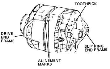
ag. Inside slip ring end frame, break off end of toothpick using pliers. Be sure
end of toothpick is even with brush holder (26).
ah. Remove protective paper tube
from slip ring end of rotor
shaft.
ai. Carefully push slip ring end
frame onto rotor (44) shaft.
Aline marks on end frames.
aj. Install four capscrews (1)
and tighten evenly.
ak. Pull toothpick straight out
of slip ring end frame to
release brushes.
al. Install alternator (refer to TM 5-3805-262-20).
3-222