INSTALLATION (SHEET 3 OF 3)
NOTE
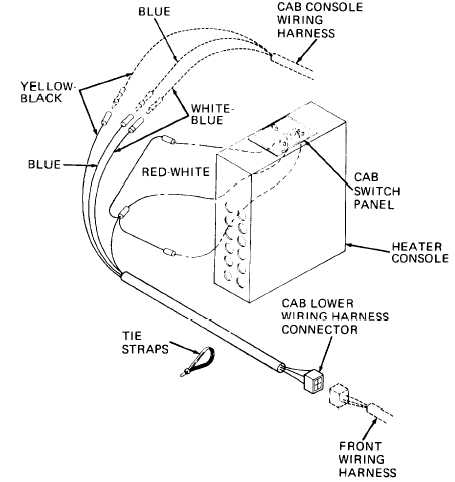
Spray all exposed
terminals with
electrical sealer and
i n s t a l l
new tie
straps at locations
noted during removal.
TM 5-3805-262-34
(8)
(9)
(10)
(11)
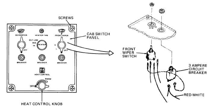
Carefully position
cab switch panel on
heater console being
careful not to pinch
wiring or disconnect
any wire connec-
tions.
Install and tighten
four screws.
Install HEAT CONTROL knob
by pushing knob firmly
down onto control shaft.
Connect battery ground cable
and test cab lower wiring
harness (refer to TM
5-3805-262-20).
3-309