TM 5-3805-262-34
13-14. STEERING GEAR MAINTENANCE (CONT)
REASSEMBLY (SHEET 3 OF 3)
u.
v.
w.
x.
y.
z.
aa.
ab.
ac.
ad.
3-522
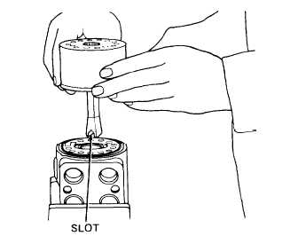
Engage drive shaft (19) teeth and
rotor (21) teeth so that slot in
end of drive shaft is between two
teeth on rotor as shown.
Install spacer plate (18) on
stator (22). Turn spacer plate to SLOT
aline holes in it with holes in
stator.
Put housing (41) in soft jawed vise with bottom end upward.
Hold spacer plate (18), drive shaft
(19), and metering gear set (21 and
22) as an assembly in position over
housing (41). Turn this assembly (18
thru 22) to put slot in end of drive
shaft (19) in alinement with pin (27)
inside valve spool (28). Lower this
assembly into position on housing
(41).
Turn spacer plate (18), drive shaft
(19), and metering gear set (21 and
22) assembly a small amount in one di-
rection or other until slot in drive
shaft is engaged with pin (27) in
valve spool (28). Turn spacer plate
and stator (22) to aline holes with
holes in housing (41).
Install spacer (17) in rotor (21) on top of drive shaft (19).
Apply oil-soluble grease to new O-ring (16). Install
O-ring in groove in end cap (15).
Install end cap (15) on stator (22). Be sure to
aline holes in end plate with holes in stator.
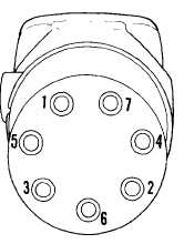
Install seven splined capscrews (14). Tighten capscrews
to 100 to 150 lb-in. in sequence shown then tighten to
225 to 275 lb-in. in same sequence.
Position steering column (13) on housing (41). In-
stall and tighten two screws (12).