
TM 5-3805-290-10
STEERING FRAME LOCK CONNECTION AND DISCONNECTION - CONTINUED
0015 00
CONNECTION
1.
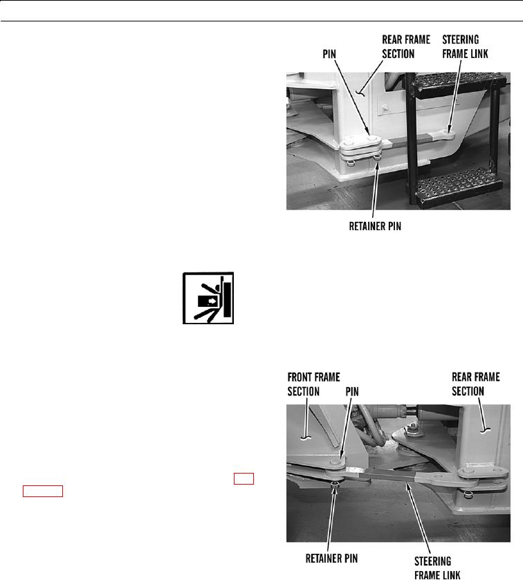
Remove retainer pin from pin.
427-B0567
2.
Move steering frame lock into position at front frame section.
WARN I N G
Stand clear of frame articulation area when machine is operating. There is no clearance for personnel
in this area when machine turns. Crushing could occur, resulting in injury or death to personnel.
N OT E
It may be necessary to move front frame section to
align pin bores.
3.
Turn ignition switch to ON position, hold auxiliary
power steering switch on, and articulate machine to
align pin bores.
4.
Install pin and retainer pin.
5.
Turn battery disconnect switch to OFF position (WP
427-B0568
DISCONNECTION
1.
Remove retainer pin from pin.
2.
Move steering frame lock to stowed position.
3.
Install pin and retainer pin.
END OF WORK PACKAGE
0015 00-2