
TM 5-3805-290-10
LIFT KICKOUT ADJUSTMENT - CONTINUED
0017 00
ADJUSTMENT - CONTINUED
N OT E
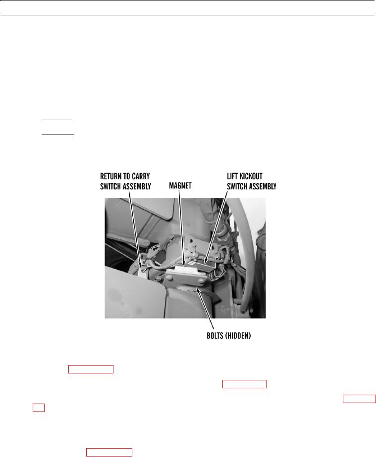
There are two switch assemblies mounted at base of loader arm. One is for lift kickout; the other is for
return to carry kickout. The lift kickout switch assembly is mounted closest to the cab.
6.
Access lift kickout switch assembly from left side of machine.
7.
Loosen two bolts and move switch assembly to position observed on step 3.
a.
If increasing lift kickout height, move switch assembly clockwise (to the right) or back.
b.
If decreasing lift kickout height, move switch assembly counterclockwise (to the left) or forward.
8.
Tighten two bolts to secure switch assembly in position.
427-B0569
9.
Test adjustment as follows:
a.
Start engine (WP 0005 00).
b.
Move joystick control lever to LIFT KICKOUT detent position (WP 0004 00).
c.
When bucket reaches preset lift kickout height, joystick control lever should return to HOLD position (WP 0004
00). Loader arm will stop moving.
d.
Repeat steps 2 thru 9 until adjustment is correct.
e.
Lower loader arm to ground.
f.
Shut down engine (WP 0005 00).
END OF WORK PACKAGE
0017 00-2