TM 5-3805-290-23-1
THEORY OF OPERATION - CONTINUED
0003 00
FUEL SYSTEM - CONTINUED
7.
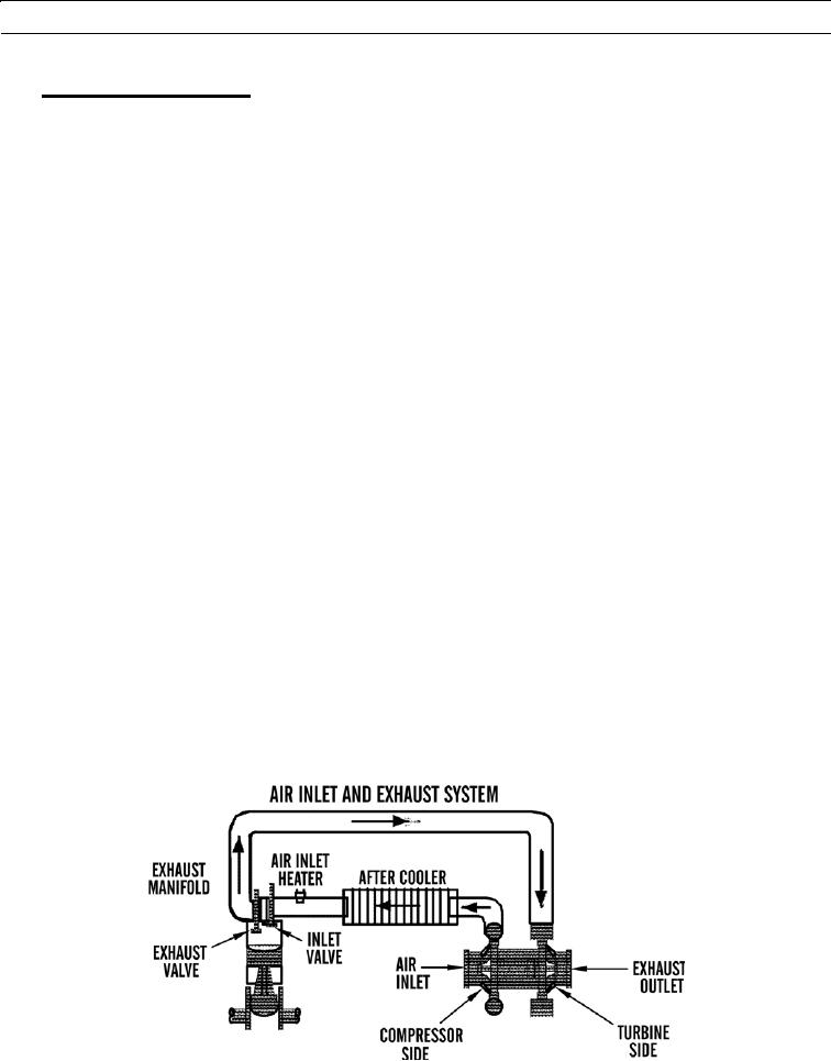
Air Inlet and Exhaust System.
a.
Air inlet and exhaust system controls quality and amount of air available for combustion. Air inlet and exhaust sys-
tem components are:
(1)
Air cleaner
(2)
Turbocharger
(3)
Aftercooler
(4)
Cylinder head
(5)
Valves and valve system components
(6)
Piston and cylinder
(7)
Exhaust manifold
b.
Air is drawn in through air cleaner into air inlet by turbocharger compressor wheel. Air is compressed and heated
to approximately 300F (150C) before being forced to aftercooler. As air flows through aftercooler, compressed
air temperature lowers to approximately 120F (50C). Cooling inlet air increases combustion efficiency.
Increased combustion efficiency helps achieve:
(1)
Lower fuel consumption
(2)
Increased horsepower output
(3)
Reduced particulate emission
c.
From aftercooler, air is forced into inlet manifold. Air flow from inlet chambers into cylinders is controlled by inlet
valves. There is one inlet valve and one exhaust valve for each cylinder. Inlet valves open when piston moves
down on intake stroke. When inlet valves open, cooled compressed air from inlet port is pulled into cylinder. Com-
plete cycle consists of four strokes:
(1)
Inlet
(2)
Compression
(3)
Power
(4)
Exhaust
d.
Exhaust gases from exhaust manifold enter turbine side of turbocharger in order to turn turbocharger turbine
wheel. Turbine wheel is connected to shaft that drives compressor wheel. Exhaust gases from turbocharger pass
through exhaust outlet, muffler, and exhaust stack.
427-B1504
0003 00-15

