
TM 5-3805-290-23-1
THEORY OF OPERATION - CONTINUED
0003 00
FUEL SYSTEM - CONTINUED
8.
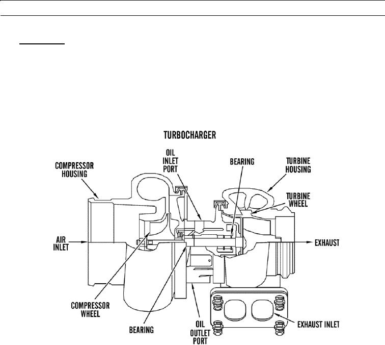
Turbocharger.
a.
Turbocharger is installed on center section or on top of exhaust manifold. All engine exhaust gases go through tur-
bocharger. Exhaust gases enter turbine housing through exhaust inlet. Exhaust gases then push turbine wheel
blades. Turbine wheel is connected to compressor wheel by a shaft.
b.
When engine load increases, more fuel is injected into cylinders. Combustion of this additional fuel produces more
exhaust gases. Additional exhaust gases cause turbocharge turbine and compressor wheels to turn faster. As com-
pressor wheel turns faster, more air is forced into cylinders. This increased flow of air gives engine more power by
allowing engine to burn additional fuel with greater efficiency.
427-B1505
0003 00-16