
TM 5-3805-290-23-1
THEORY OF OPERATION - CONTINUED
0003 00
BRAKE SYSTEM - CONTINUED
3.
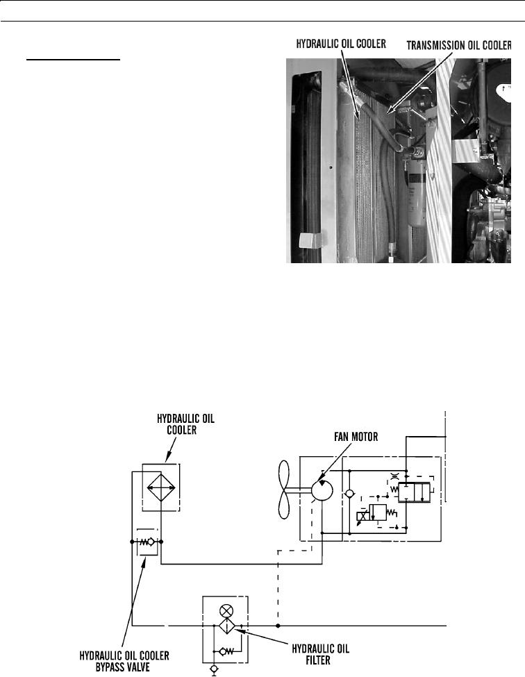
Hydraulic Oil Cooler.
a.
Hydraulic oil cooler is located directly in front of
hydraulic fan. Hydraulic oil cooler provides
cooling for all hydraulic systems that use oil
from hydraulic oil tank.
b.
Hydraulic oil cooler is located next to transmis-
sion oil cooler inside radiator door.
c.
Hydraulic oil cooler keeps hydraulic oil at cor-
rect operating temperature.
427-B1543
d.
Oil flows from hydraulic fan motor to hydraulic oil cooler. After oil is cooled, oil flows to hydraulic oil filter.
Then, oil is returned to tank.
e.
If pressure differential between inlet and outlet of hydraulic oil cooler exceeds 30 psi (207 kPa), oil cooler bypass
valve will divert oil around hydraulic oil cooler.
f.
These conditions could cause oil cooler bypass valve to divert oil around hydraulic oil cooler:
(1)
Cold hydraulic oil
(2)
Restriction in a hydraulic oil line
(3)
Restriction in hydraulic oil cooler
427-B1544
0003 00-105