TM 5-3805-290-23-1
THEORY OF OPERATION - CONTINUED
0003 00
BRAKE SYSTEM - CONTINUED
5.
Gear Motor (Hydraulic Fan).
a.
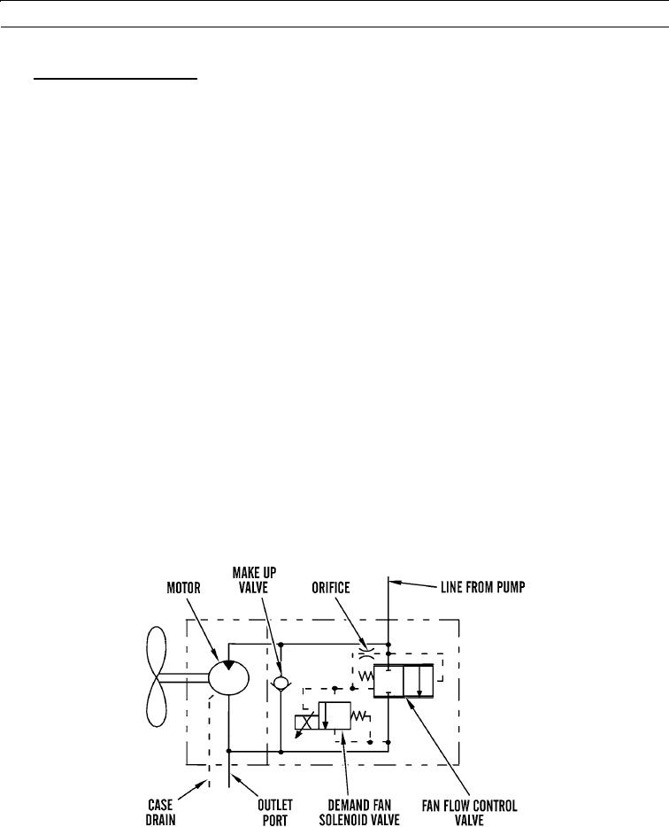
Hydraulic fan motor is a gear type motor located behind radiator. Hydraulic fan motor drives radiator fan. Fan
draws cooling air through radiator and hydraulic oil cooler. Hydraulic oil for hydraulic fan motor is provided by
gear pump.
b.
When machine is started, oil flows into hydraulic fan motor through line from pump. Hydraulic oil flows into a
cavity formed by gears. Hydraulic oil pressure forces gears and output shaft to rotate.
c.
Fan is attached to output shaft by an adapter. Output shaft rotation causes fan to rotate. As gears rotate, hydraulic
oil passes through outlet port and oil flows out of motor.
d.
Hydraulic fan motor is equipped with a demand fan solenoid valve, a flow control valve, and a makeup valve.
Demand fan solenoid valve is controlled by machine ECM, which sends a signal to demand fan solenoid valve to
control fan speed. When machine ECM sends a maximum signal to demand fan solenoid valve, pressure drop
across orifice increases and flow control valve opens. Fan speed is at minimum because flow control valve is
diverting oil flow from pump around motor. When machine ECM sends a minimum signal to demand fan solenoid
valve, pressure drop across orifice decreases and flow control valve closes. Fan speed is at maximum because flow
control valve is no longer diverting oil flow around motor.
e.
Machine ECM will send required signal to demand fan solenoid valve to provide proper fan speed for cooling sys-
tem. In order to provide proper fan speed, machine ECM will monitor:
(1)
Coolant temperature
(2)
Hydraulic oil temperature
(3)
Transmission oil temperature
(4)
Air inlet temperature
f.
Makeup valve prevents hydraulic fan motor cavitation. During a quick deceleration, oil flow to fan motor can stop.
Makeup valve opens to allow oil to flow from outlet side of hydraulic fan motor to inlet side of fan motor.
g.
Case drain, drains oil from motor to tank.
427-B1548
0003 00-108

