
TM 5-3805-290-23-1
THEORY OF OPERATION - CONTINUED
0003 00
BRAKE SYSTEM - CONTINUED
7.
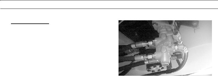
Brake Control Valve.
a.
Service brake control valve is located under front
side of operator's cab.
b.
A mechanical link connects two brake pedals to
each other. When a brake pedal is pressed, a
roller on cross shaft assembly actuates service
brake control valve. Control valve is a dual pres-
sure reducing valve with two independent output
pressures.
427-B1555
0003 00-110