TM 5-3805-290-23-1
THEORY OF OPERATION - CONTINUED
0003 00
HYDRAULIC SYSTEM - CONTINUED
14.
Relief Valve (Line).
N OT E
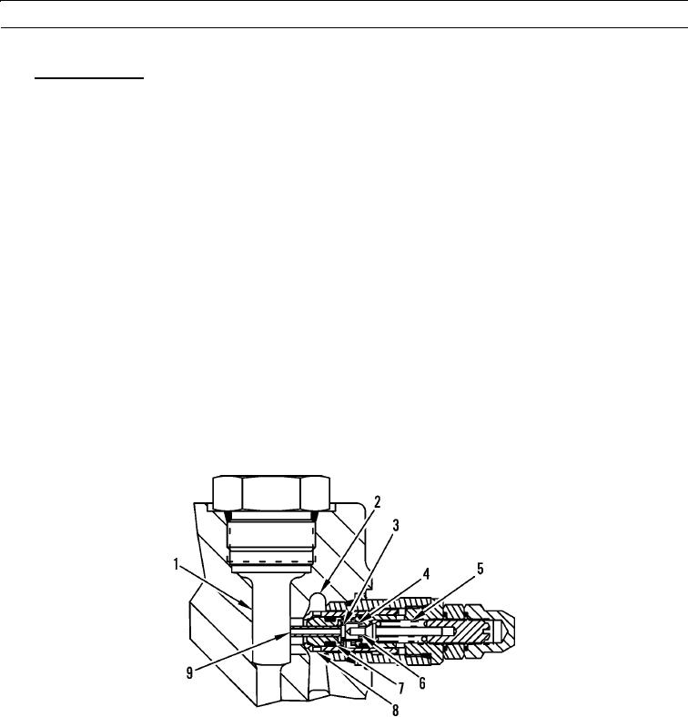
A typical view of a pilot operated makeup and relief valve.
a.
The makeup and relief valves in the main control valves are pilot operated relief valves. Hydraulic oil in passage
(1) flows through passage (9) to spring chamber (3). When the pressure of the hydraulic oil in the spring chamber
overcomes the force of spring (5), the relief valve opens.
b.
Valve (6) moves to the right. When the valve moves, hydraulic oil in the spring chamber is released. Hydraulic oil
in passage (1) moves relief valve (7) to the right. This opens port (8).
c.
Some of the hydraulic oil from chamber (1) flows through passage (9) to passage (2). The hydraulic oil flows to the
tank. To prevent cavitation, the relief valve also provides makeup oil to the return circuit. Hydraulic oil in the
return circuit acts against the relief valve (7). The relief valve moves to the right. The hydraulic oil flows from pas-
sage (2) to passage (9).
d.
The makeup and relief valve for the head end of the tilt cylinder functions only as a makeup valve. The makeup
and relief valve for the head end of the tilt cylinder is located on the main control valve next to the block valve for
the head end of the tilt circuit. The relief valve on the combination valve acts as the relief valve for the head end of
the tilt cylinder.
e.
The makeup and relief valve for the rod end of the tilt cylinder is located next to the block valve for the rod end of
the tilt cylinder. To prevent cavitation, the makeup and relief valve provides hydraulic oil to the rod end of the tilt
cylinder. Also, the makeup and relief valve drains the hydraulic oil to the tank when the hydraulic oil pressure in
the hydraulic circuits gets too high.
427-B1782
0003 00-190

