
TM 5-3805-290-23-1
THEORY OF OPERATION - CONTINUED
0003 00
AIR CONDITIONING SYSTEM
0003 00
General
1.
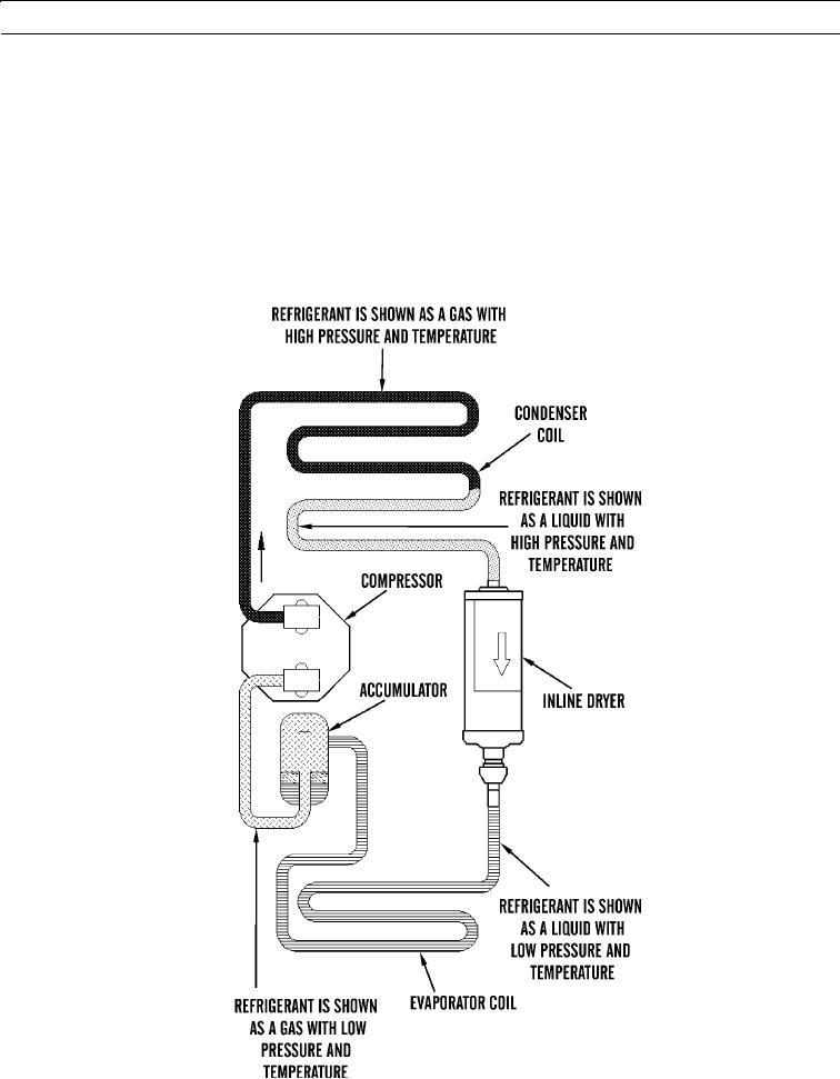
The orifice tube system uses an orifice tube in place of the expansion valve. The accumulator and the inline dryer with
orifice tube replace the receiver/dryer.
2.
The orifice tube assembly is located in one end of the inline dryer. The inline dryer is located in the line that goes from
the condenser coil to the evaporator coil.
3.
The desiccant is located in the inline dryer. The accumulator is located in the line that extends from the evaporator coil
to the compressor. The orifice tube assembly is before the inlet of the evaporator coils.
427-B2081