TM 5-3805-290-23-1
TRANSMISSION TESTS, INSPECTIONS, AND ADJUSTMENTS - CONTINUED
0014 00
TRANSMISSION CONTROL (SHIFT LEVER) TEST - CONTINUED
10.
Check ECM.
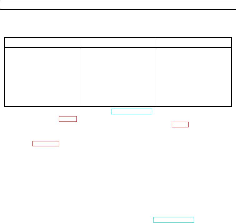
Table 4. Machine ECM Connector Pin Assignments.
Function
Wire Assignment
Machine ECM Pin Assignments
Forward
G750-BU
Connector J2, Pin 49
Neutral
G763-PU
Connector J2, Pin 23
Reverse
G755-GY
Connector J2, Pin 28
First Gear
G768-GN
Connector J2, Pin 50
Second Gear
G760-WH
Connector J1, Pin 41
Third Gear
G761-YL
Connector J1, Pin 42
Fourth Gear
G762-BR
Connector J1, Pin 43
a.
Turn battery disconnect switch to OFF position (TM 5-3805-290-10).
b.
Using information in Table 4, remove corresponding wires from machine ECM harness connectors J1 and J2.
Also, use shifter schematic for reference. After removing all wires shown in Table 4, momentarily connect to
frame ground individually. Ensure wires cannot accidentally touch frame ground.
c.
Turn service disconnect switch to ON position. Start machine with key in RUN position, and connect and start up
MSD (WP 0006 00).
d.
Select powertrain ECM and go to status screen 4.
e.
Monitor status of shifter on MSD screen.
f.
Expected Results. As each combination of contacts is grounded, MSD screen displays corresponding shifter posi-
tion.
(1)
If results are OK, ECM is working properly. Wiring harness may have failed. Replace wiring harness in
question (WP 0169 00 thru WP 0175 00).
(2)
If results are NOT OK, ECM may have failed. Clean contacts for ECM harness connectors. It is unlikely
that ECM has failed. Exit this procedure and perform entire procedure again. If problem remains, replace
ECM. It is preferable to show new ECM corrects problem and suspect ECM demonstrates problem.
11.
Verify shift lever remote F/N/R switch functionality.
a.
Place shift lever on steering column in NEUTRAL and FIRST GEAR (TM 5-3805-290-10).
b.
At shifter 4-pin connector, remove jumper wire between pin 3 and pin 4.
c.
Connect 4-pin receptacle connector CN-C50 from cab harness to shifter 4-pin plug (WP 0081 00). This will enable
remote F/N/R switch circuit for shift lever.
d.
Ensure pins and sockets are seated properly and connector mates correctly.
e.
Place remote F/N/R switch in FORWARD position.
f.
Verify MSD shows "F1" as desired gear.
g.
Place remote F/N/R switch in REVERSE position.
h.
Verify MSD shows "R1" as desired gear.
i.
Expected Results. As each combination is switched, MSD screen displays corresponding gear and direction.
(1)
If status of shift lever position changes properly, monitor machine to check if problem occurs. If problem
occurs, repeat entire test procedure.
0014 00-15

