TM 5-3805-290-23-2
AIR RESTRICTION INDICATOR AND HOSE REPLACEMENT - CONTINUED
0031 00
REMOVAL
00031 00
1.
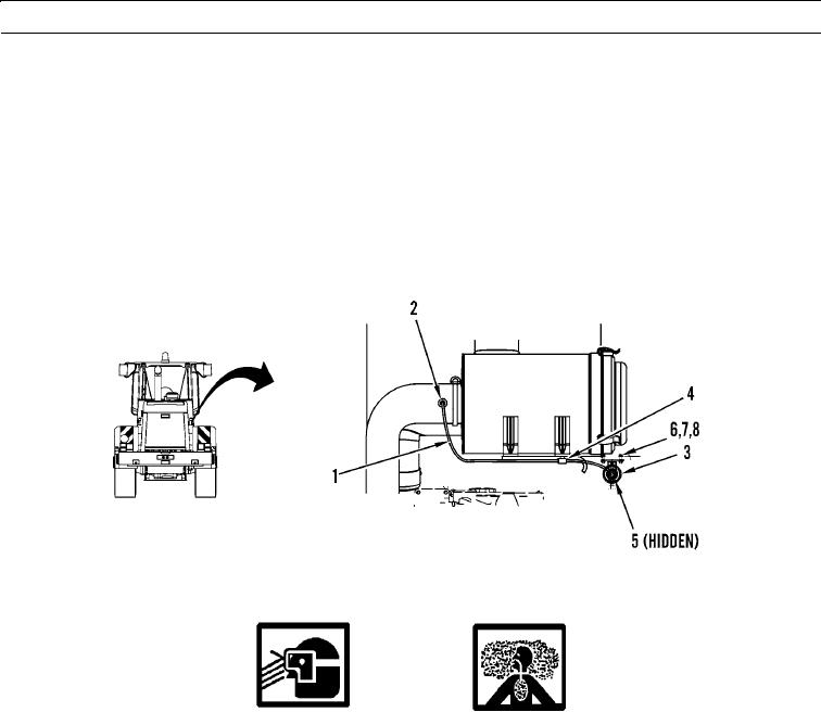
Disconnect hose (1) from fitting (2) and restriction indicator (3).
N OT E
Note location of any tiedown straps to ensure correct installation.
2.
Trace routing of hose (1) and remove and discard any tiedown straps holding hose in place.
3.
Slide hose (1) out of clip (4) and remove hose from machine.
4.
Disconnect wiring harness (5) from restriction indicator (3).
5.
Remove two screws (6), nuts (7), four washers (8), and restriction indicator (3) from machine.
427-B1829
CLEANING AND INSPECTION
WARN I N G
Particles blow by compressed air are hazardous. DO NOT exceed 15 psi (103 kPa) nozzle pressure when
drying parts with compressed air. DO NOT direct compressed air against human skin. Failure to follow
this warning may result in injury to personnel. Make sure air steam is directed away from user and other
personnel in the area. To prevent injury, user must wear protective goggles or face shield.
1.
Clean all parts with detergent and water solution.
2.
Dry parts with compressed air.
3.
Inspect all parts for wear, pitting, cracks, or corrosion and replace if necessary.
00031 00
INSTALLATION
1.
Install restriction indicator (3), four washers (8), two screws (6), and nuts (7) on machine.
2.
Connect wiring harness (5) to restriction indicator (3).
3.
Slide hose (1) through clip (4) and connect hose to restriction indicator (3) and fitting (2).
4.
Install new tiedown straps on hose (1) as necessary.
END OF WORK PACKAGE
0031 00-2

