TM 5-3805-290-23-2
CYLINDER HEAD REPLACEMENT - CONTINUED
0146 00
CLEANING AND INSPECTION - CONTINUED
3.
Inspect all parts for wear, pitting, cracks, or corrosion and replace if necessary.
4.
Inspect oil passages to ensure they are clean and unobstructed.
5.
Clean bottom face of cylinder head thoroughly (WP 0023 00). Clean coolant passages and lubricating oil passages.
Ensure contact surfaces of cylinder head and cylinder block are clean, smooth, and flat.
6.
Inspect bottom face of cylinder head for pitting, corrosion, and cracks. Carefully inspect area around valve seat inserts
and holes for fuel injection nozzles.
7.
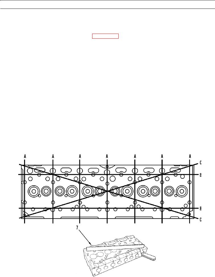
Measure cylinder head (7) for flatness. Measure flatness with straightedge and angle gage.
Measure cylinder head from one side to opposite side (A).
Measure cylinder head from one end to opposite end (B).
Measure cylinder head from one corner to opposite corner (C).
N OT E
Maximum permissible projection of fuel injection nozzle (below face of cylinder head after resurfacing) is
0.1205 in. (3.06 mm).
8.
Use angle gage and straightedge to measure projection of fuel injection nozzles.
9.
Use angle gage and straightedge to ensure minimum permissible cylinder head face thickness after resurfacing is 4.035
in. (102.5 mm).
10.
Measure maximum distortion of cylinder head (7) using dimensions shown below.
a.
Maximum distortion of "A" is 0.005 in. (0.13 mm).
b.
Maximum distortion of "B" and "C" is 0.009 in. (0.23 mm).
427-B0364
427-B0646
0146 00-6

