TM 5-3805-290-23-2
CRANKSHAFT VIBRATION DAMPER AND PULLEY REPLACEMENT - CONTINUED
0147 00
INSTALLATION - CONTINUED
N OT E
On some engines, damper is placed on rear of pulley. Fit inner flange of damper to rear of pulley.
5.
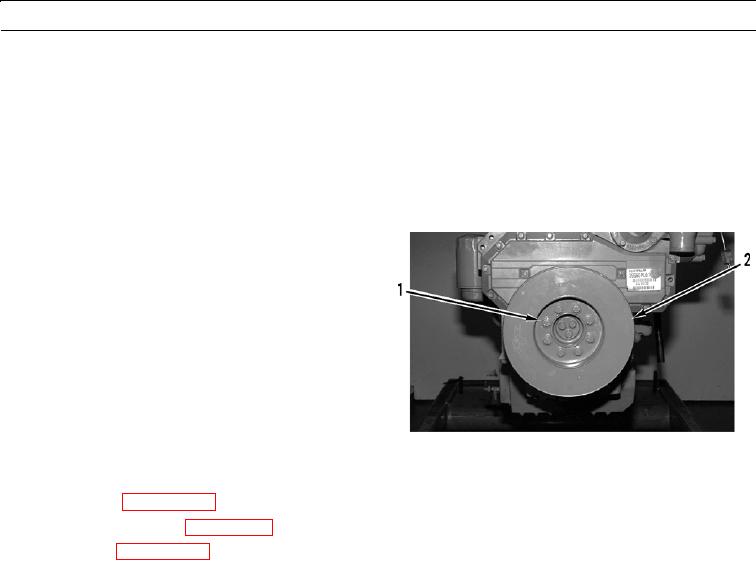
Position crankshaft vibration damper (2) for bolt holes to align with pulley.
N OT E
Apply sealing compound to bolts when installing vibration damper.
6.
Install bolts (1) and tighten evenly. Gradually tighten
bolts to final torque of 25 lb-ft (34 Nm).
427-B0360
7.
Check oil level (WP 0025 00).
8.
Install fan and fan group (WP 0168 00).
9.
Install V-belts (WP 0046 00).
10.
Run engine until normal operating temperature is reached (TM 5-3805-290-10).
11.
Check operation.
12.
Shut down engine (TM 5-3805-290-10).
ADJUSTMENT
1.
Use lever to carefully move vibration damper forward to eliminate end play of crankshaft.
2.
Position dial indicator on front cover, set dial indicator to read 0.00 in. (0.00 mm), and measure outer face of vibration
damper.
3.
Rotate crankshaft and read dial indicator at 90 degree intervals.
4.
Difference between lower and higher measurements must not be more than 0.007 in. (0.18 mm).
5.
If readings are more than 0.007 in. (0.18 mm), inspect pulley and vibration damper for damage. Replace damaged com-
ponent(s).
6.
Position dial indicator to measure circumference of vibration damper. Set indicator to 0.00 in. (0.00 mm).
7.
Slowly rotate crankshaft to measure runout of circumference of vibration damper. Maximum and minimum readings
should not vary more than 0.005 in. (0.13 mm).
8.
If readings vary more than 0.005 in. (0.13 mm), inspect pulley and vibration damper for damage. Replace damaged
component(s).
END OF WORK PACKAGE
0147 00-6

