
TM 5-3805-291-23-1
THEORY OF OPERATION - CONTINUED
0003 00
BRAKE AND HYDRAULIC FAN SYSTEM - CONTINUED
3.
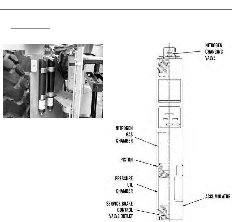
Brake Accumulator.
427-C1758
427-C1759
a.
Accumulators for both front and rear service brakes are located behind ladder on right side of machine. Accumula-
tors are mounted in a vertical position. Accumulator for front service brakes is positioned outside of accumulator
for rear service brakes.
b.
Both service brake accumulators have a piston, which is sealed. Piston moves back and forth inside accumulator
bore. Nitrogen gas chamber contains a charge of approximately 900 psi (6,205 kPa) of dry nitrogen gas. Dry nitro-
gen gas is added to accumulator through nitrogen charging valve.
c.
Oil from accumulator charging valve flows through outlet, then enters pressure oil chamber. Oil then pushes pis-
ton, causing dry nitrogen gas to compress. When pressure in accumulator reaches cutout pressure, oil supply is
stopped by accumulator charging valve.
d.
When a brake pedal is pushed, oil from chamber flows outward through outlet to service brake control valve,
where oil applies service brakes.
0003 00-82