
TM 5-3805-291-23-1
THEORY OF OPERATION - CONTINUED
0003 00
BRAKE AND HYDRAULIC FAN SYSTEM - CONTINUED
(1)
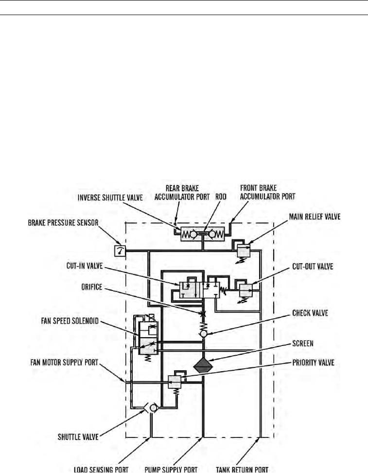
Brake Operation Below Cut-In Pressure.
(a) Cut-in valve controls minimum braking system pressure. When service brake pressure is below cut-in
pressure, cut-in valve allows pressurized oil to flow to shuttle valve. Shuttle valve shifts left and
allows pressurized oil to exit load sensing port to upstroke pump. Pressurized oil and spring pressure
hold priority valve closed. Full pump flow is directed to brake section of control manifold to satisfy
brake system demand.
(b) Pump flow enters control manifold through pump supply port. Pump flow passes through screen,
check valve, and orifice to inverse shuttle valve. Inverse shuttle valve senses brake accumulator port
that has highest pressure. Accumulator port with highest pressure seats check valve. Rod opens check
valve with lowest accumulator pressure. Brake accumulator can be charged with check valve in open
position. Brake pressure sensor senses pressure in brake accumulators. When pressure is low, sensor
activates a warning lamp (TM 5-3805-291-10).
427-C1763
0003 00-86