
TM 5-3805-291-23-1
THEORY OF OPERATION - CONTINUED
0003 00
ELECTRO-HYDRAULIC SYSTEM - CONTINUED
c.
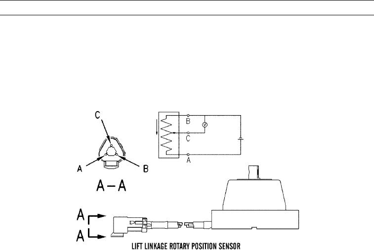
Lift Linkage Rotary Position Sensor.
(1)
Lift linkage position sensor is an implement ECM input which continuously communicates lift linkage
position to ECM. ECM changes lift linkage position by activating lift lower solenoid and lift raise sole-
noid. Changes are based on joystick position. ECM uses lift linkage sensor input to control lift kickouts.
ECM uses sensor input to cushion lift linkage stops. This position sensor has one input connection to ECM
at connector contact J2-32.
427-C1820
(2)
Lift linkage position sensor is a PWM sensor. When ECM receives PWM signal, it measures duty cycle to
determine joystick position. When lift linkage is at fully raised position, duty cycle should be less than 90
percent. When lift linkage is at full lower position, duty cycle should never be below 10 percent. Fre-
quency of this sensor signal is constant at approximately 500 Hz. Machine electrical system provides +bat-
tery voltage to lift linkage position sensor for operating power.
0003 00-152