TM 5-3805-291-23-1
HYDRAULIC SYSTEM TESTS, INSPECTIONS, AND ADJUSTMENTS - CONTINUED
0017 00
RELIEF VALVE (LINE) TEST AND ADJUSTMENT - CONTINUED
Testing Line Relief Valves (Auxiliary) - Continued
N OT E
In the following steps, do not keep auxiliary control lever in full FORWARD or REARWARD position for
more than five seconds while pressure is at relief setting.
6.
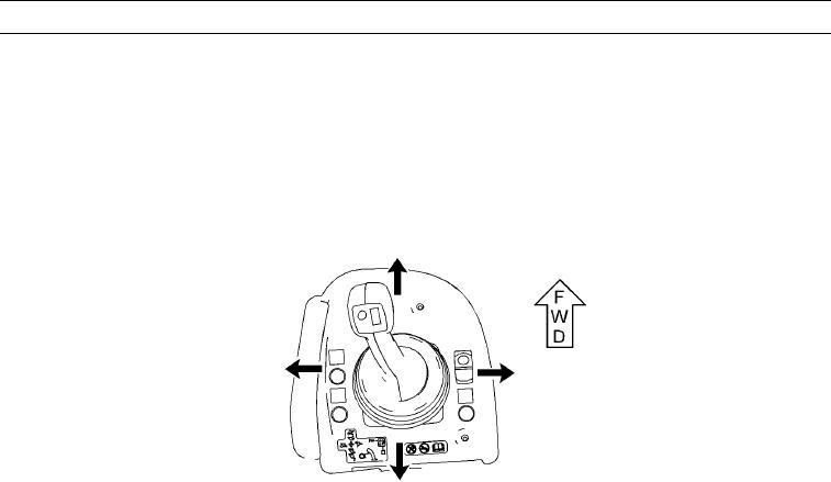
Place auxiliary control lever in full FORWARD position (TM 5-3805-291-10).
427-C0783
7.
Record opening pressure for auxiliary line relief valve.
8.
Place auxiliary control lever in full REARWARD position (TM 5-3805-291-10).
N OT E
Auxiliary line relief valve pressure should be3,000 50 psi (20,680 345 kPa).
If pressure readings are not wthin specification, proceed to Line Relief Valves Adjustment in this
i
work package.
9.
Record opening pressure for auxiliary line relief valve.
10.
Stop engine (TM 5-3805-291-10).
11.
Ensure control levers are in HOLD position (TM 5-3805-291-10).
12.
To relieve pressure in hydraulic tank (22), press and hold plunger on breaker relief valve (23).
0017 00-63

