
TM 5-3805-291-23-2
TRANSMISSION HYDRAULIC CONTROL RELIEF VALVE REPLACEMENT - CONTINUED
0202 00
REMOVAL
C AU T I O N
Wipe area clean around all connections to be opened during removal. Cap lines and hoses and plug open-
ings after removing lines. Contamination of system could result in premature failure.
N OT E
Tag hoses prior to removal to ensure correct installation.
Use a container to catch any fluid that may drain from hoses or system. Dispose of fluid IAW local pol-
icy and ordinances. Ensure all spills are cleaned up.
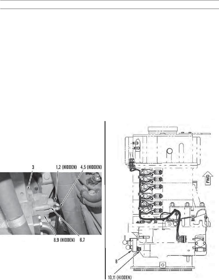
The transmission hydraulic control relief valve is located on the left rear side of the transmission hous-
ing.
1.
Disconnect hose assembly (1) and remove O-ring (2) from transmission (3). Discard O-ring.
2.
Disconnect hose assembly (4) and remove O-ring (5) from transmission (3). Discard O-ring.
3.
Remove four bolts (6), washers (7), transmission hydraulic control relief valve (8), and O-ring (9) from transmission (3).
Discard O-ring.
4.
Remove torque converter inlet relief valve (10) and O-ring (11) from transmission (3). Discard O-ring.
427-C1002
427-C1003
0202 00-2