
TM 5-3805-291-23-2
TRANSMISSION OIL PUMP (GEAR PUMP) REPLACEMENT - CONTINUED
0206 00
INSTALLATION - CONTINUED
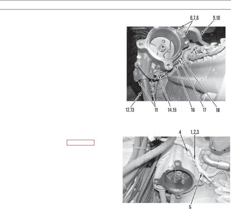
4.
Install bracket (18) and bolt (17).
5.
Connect sensor (16) and install washer (15) and bolt
(14).
6.
Lubricate new O-ring (13) with clean oil and install on
tube assembly (12).
7.
Install two bolts (11) on tube assembly (12).
8.
Lubricate new O-ring (10) and install on hose assem-
bly (9).
9.
Connect hose assembly (9), two flange halves (8), four
washers (7), and bolts (6).
427-C1967
10.
Position wiring harness (5) and install bracket (4), clip
(3), washer (2), and bolt (1).
11.
Install implement piston pump (WP 0216 00).
427-C1000
WAR N I N G
Before operating the machine, secure the steering frame lock in the stowed position. DO NOT operate
machine with steering frame lock connected. Failure to lock steering frame lock into the stowed position
before operating can result in loss of steering and injury or death to personnel.
12.
Secure steering frame lock in stowed position (TM 5-3805-291-10).
13.
Start machine (TM 5-3805-291-10).
14.
Run engine until operating temperature is reached and verify correct operation of machine (TM 5-3805-291-10).
15.
Check oil level (TM 5-3805-291-10).
16.
Shut down engine (TM 5-3805-291-10).
17.
Check transmission for leaks.
END OF WORK PACKAGE
0206 00-4