
TM 5-3805-291-23-2
BUCKET TILT LEVER AND LINK REPLACEMENT - CONTINUED
0228 00
INSTALLATION - CONTINUED
Tilt Lever - Continued
0228 00
C AU T I O N
Aligning bores of tilt lever and bucket tilt link is important. Improper alignment can damage lip seals dur-
ing installation of pin assembly.
N OT E
Perform steps 8 and 9 on right side of
machine.
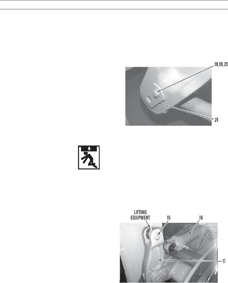
8.
Install pin assembly (21) on machine.
9.
Install spacer (20), washer (19), and bolt (18) in pin
assembly (21).
427-C1133
WARN I N G
Use extreme caution when handling heavy parts. Provide adequate support and use assistance during pro-
cedure. Ensure that any lifting equipment used is in good condition and of suitable load capacity. Keep
clear of heavy parts supported only by lifting equipment. Failure to follow this warning may result in injury
or death to personnel.
N OT E
Tilt cylinder weighs 485 lb (220 kg).
10.
Use lifting equipment to raise rod end of tilt lever (17).
11.
Start engine (TM 5-3805-291-10) and extend tilt lever
(17).
12.
With assistance, align bore of tilt lever (17) with pin
bore of tilt cylinder (16) and install pin assembly (15)
in pin bore.
427-C1132
0228 00-12