
TM 5-3805-292-10
0004
OPERATOR CONTROLS AND INDICATORS CONTINUED
1
2
3
458-0138
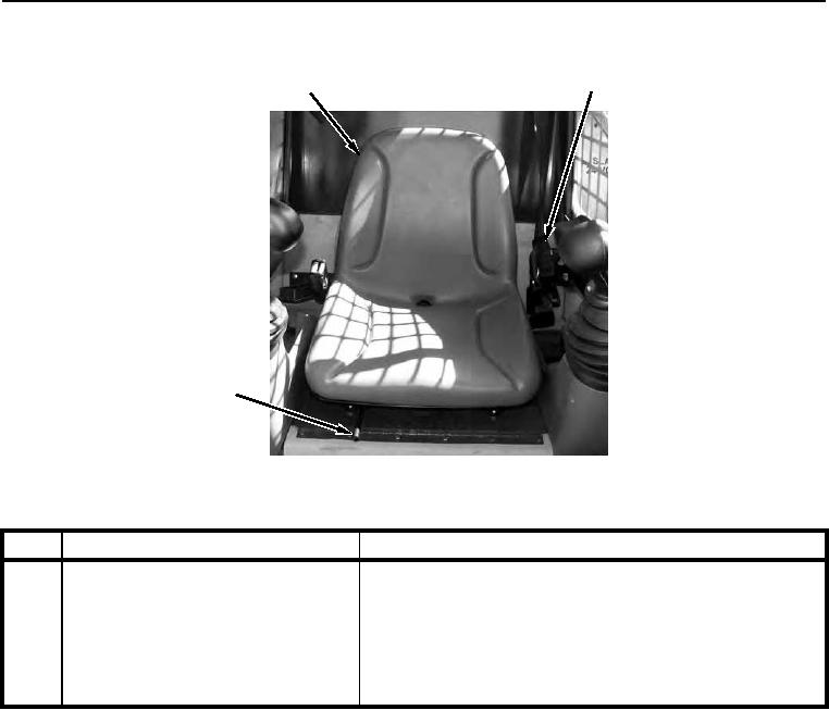
Figure 13. Operator Seat and Seat Belt.
0004
KEY
COMPONENT
DESCRIPTION
1
Operator Seat
Operator must be seated to close operator presence switch.
Closing switch powers DIP.
2
Seat Belt
Operator must pull seat belt across body and buckle securely
while seated. Seat belt must be fastened to release parking
brake.
3
Seat Forward/Aft Adjustment Lever
Adjusts seat to desired position.
END OF WORK PACKAGE
0004-13/(14 blank)