
TM 5-3805-292-10
0004
OPERATOR CONTROLS AND INDICATORS CONTINUED
1
2
3
458-0107
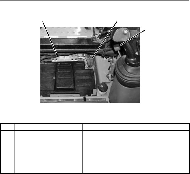
Figure 7. Throttle and Auxiliary Hydraulic Controls.
0004
KEY
COMPONENT
DESCRIPTION
1
Auxiliary Hydraulic Control Pedal
Controls hydraulic oil flow to front attachment.
2
Foot Throttle
Provides a means to vary RPM. When foot throttle is
completely released, minimum speed will default to setting of
hand throttle.
3
Hand Throttle Control Lever
Lever will remain in position selected by operator. Full throttle
position allows for increased drive and loader speed and
response. Hand throttle provides a way to set a fixed engine
RPM.